
Global manufacturing method for source-drain metal of carbon nanotube device

A technology of carbon nanotubes and production methods, which is applied in the field of overall production of carbon nanotube device source and drain metals, to achieve the effect of eliminating influence and reducing deposition thickness

Active Publication Date: 2020-02-07
BEIJING INST OF CARBON BASED INTEGRATED CIRCUIT +1
View PDF7 Cites 2 Cited by
  • Summary
  • Abstract
  • Description
  • Claims
  • Application Information

AI Technical Summary

Problems solved by technology

For carbon nanotube devices, the contact metal in the source and drain regions cannot form an alloy similar to silicide with the underlying carbon nanotubes, so that it exhibits characteristics similar to the metal on the sidewall surface. It is difficult for wet etching technology to obtain very high selectivity between the two, and then remove the metal material deposited on the surface of the side wall and side wall
[0005] Therefore, the effective formation of source-drain region contact metals has become one of the biggest differences in the manufacturing process of carbon nanotube devices compared with traditional silicon-based devices, and it is also one of the biggest difficulties faced in the manufacturing process of carbon nanotube devices. The biggest challenge is how to remove the metal material deposited on the surface of the side wall, so as to effectively form the contact metal of the source and drain regions of the carbon nanotube device, which has become a major challenge restricting the development of the carbon nanotube device.

Method used


Image

  • Global manufacturing method for source-drain metal of carbon nanotube device
  • Global manufacturing method for source-drain metal of carbon nanotube device
  • Global manufacturing method for source-drain metal of carbon nanotube device

Examples


Embodiment Construction

[0041] Embodiments of the present invention will be described in detail below with reference to the accompanying drawings. In the various drawings, the same elements are denoted by the same reference numerals, and various parts in the drawings are not drawn to scale. Also, some well-known parts may not be shown. For the sake of simplicity, the semiconductor structure obtained after several steps can be described in one figure.

[0042] It should be understood that when describing the structure of a device, when a layer or a region is referred to as being "on" or "over" another layer or another region, it may mean being directly on another layer or another region, or Other layers or regions are also included between it and another layer or another region. And, if the device is turned over, the layer, one region, will be "below" or "beneath" the other layer, another region.

[0043] If it is to describe the situation directly on another layer or another area, the expression "...


PUM


Abstract

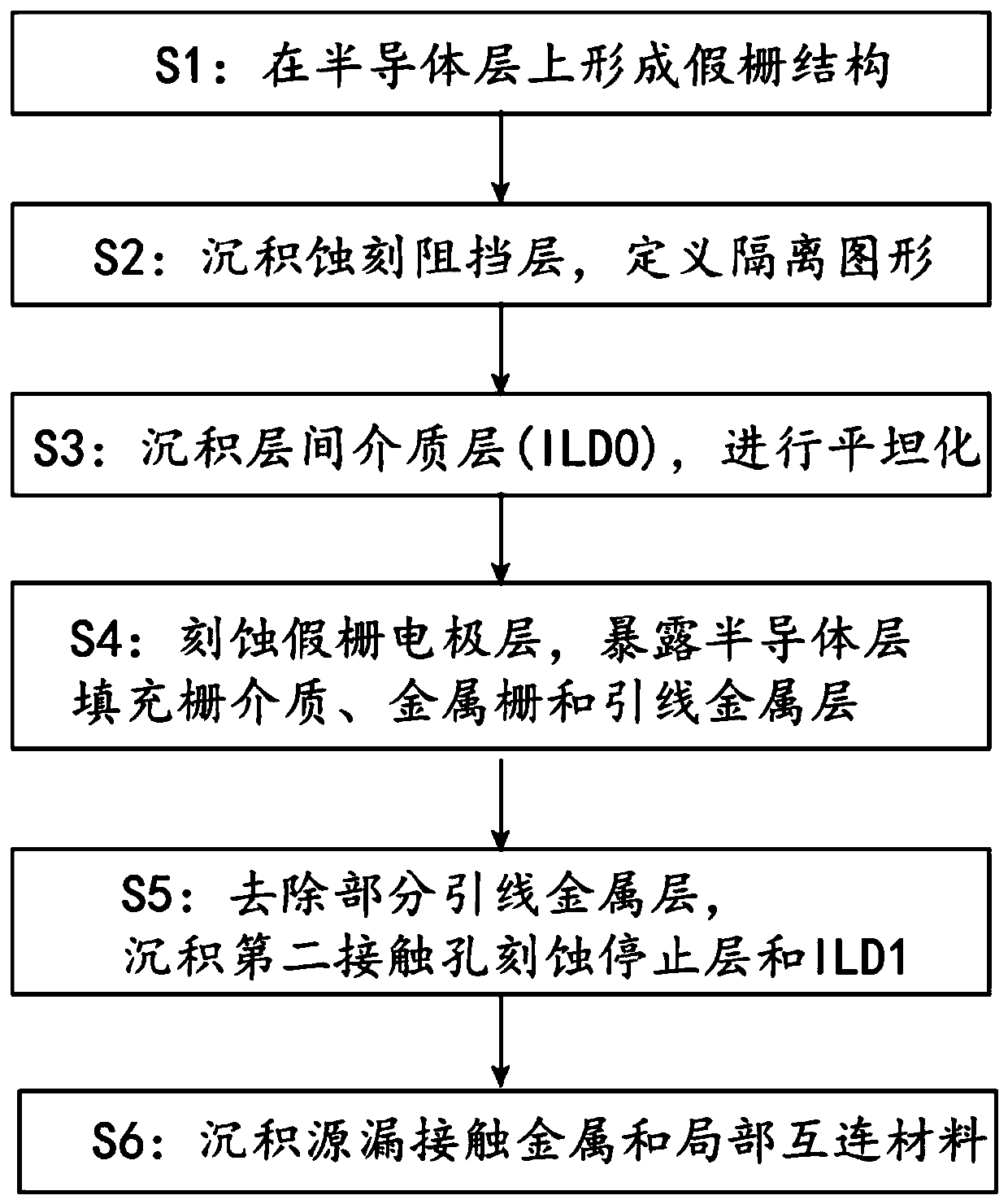
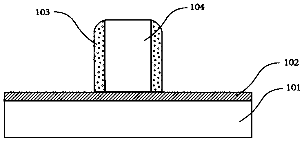
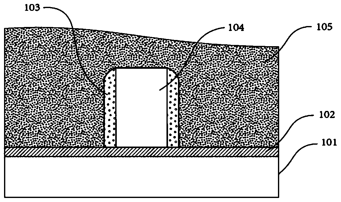
The invention discloses a global (one-time) manufacturing method for contact metal of a source region and a drain region of a carbon nanotube device. The method comprises the following steps: an interlayer dielectric layer is deposited on a dummy gate structure, and flattening is carried out to remove the inclined side wall parts on the two sides of the top of the dummy gate structure; a dummy gate in a groove structure is removed; a gate dielectric, a metal gate and a lead metal layer are sequentially deposited, and flattening is carried out to further remove the inclined side wall parts on the two sides of the top of the gate so as to form side walls only having vertical side wall surfaces; a source-drain metal pattern is defined, a source-drain contact metal layer is deposited, and theresidual metal layer on the surface of the spacer is selectively removed; an etching stop layer and a second interlayer dielectric layer are sequentially deposited, and flattening is carried out; anda source-drain contact hole and a gate lead metal layer contact hole are formed and filled with metal. The method can eliminate the influence of the morphology of the inclined side walls on the two sides of the top of the gate on the deposition of the source-drain metal, and remarkably reduces the deposition thickness of the source-drain metal on the surfaces of the side walls.

Description

technical field [0001] The invention relates to a carbon nanotube CMOS integrated circuit technology, in particular to a global manufacturing method for source and drain metals of a carbon nanotube device. Background technique [0002] As semiconductor technology continues to shrink down to technology nodes below 3nm, silicon-based integrated circuits are very likely to reach the limits of silicon materials and physical quantum mechanics. The continuous development of microelectronics urgently needs to find new materials with more potential and advantages to replace silicon materials and break through the limit of Moore's law. Carbon nanotubes (CNTs) have ultra-high carrier mobility, mean free path, and nanoscale diameter, and can be used to build nano-semiconductor devices with faster speed, lower power consumption, and smaller size. Therefore, carbon nanotubes Tube (CNTs) electronics is considered to be one of the future information technologies most likely to replace sil...

Claims


Application Information

Patent Timeline
IPC IPC(8): H01L51/05H01L51/10H01L51/40
CPCH10K71/60H10K85/221H10K10/464H10K10/84
Inventor 孟令款张志勇彭练矛
Owner BEIJING INST OF CARBON BASED INTEGRATED CIRCUIT
Learn More