One-bit digital coding antenna unit and digital phase array antenna system

A technology for phased array antennas and antenna units, which is applied to specific array feeding systems, antenna arrays, and antenna arrays that are energized separately, and can solve problems that cannot meet conformal and integrated design requirements, limit antenna usage scenarios, and reduce The overall efficiency of the antenna and other issues can be avoided to avoid energy leakage, reduce the profile and volume, and reduce the thickness.

Active Publication Date: 2020-02-07
SHANGHAI AEROSPACE ELECTRONICS CO LTD +1
View PDF12 Cites 23 Cited by
  • Summary
  • Abstract
  • Description
  • Claims
  • Application Information

AI Technical Summary

Problems solved by technology

In the traditional phased array antenna system, in order to realize the dynamic scanning of the beam and other functions, a large number of phase shifters and corresponding complex control networks need to be used in the T/R component, and the phase of the antenna unit is changed by the phase shifter, and then Control the antenna pattern so that its beam points to a specific target, the overall complexity and cost of the system are extremely high
The phased array antennas based on reflective or transmissive coded metasurfaces proposed in recent years can also realize dynamic beam scanning through the coded metasurface’s control function for incident electromagnetic waves, and effectively reduce the cost of t

Method used


Image

  • One-bit digital coding antenna unit and digital phase array antenna system
  • One-bit digital coding antenna unit and digital phase array antenna system
  • One-bit digital coding antenna unit and digital phase array antenna system

Examples


Embodiment 1

[0037] Embodiment 1: direct radiation type one-bit digital coding antenna unit

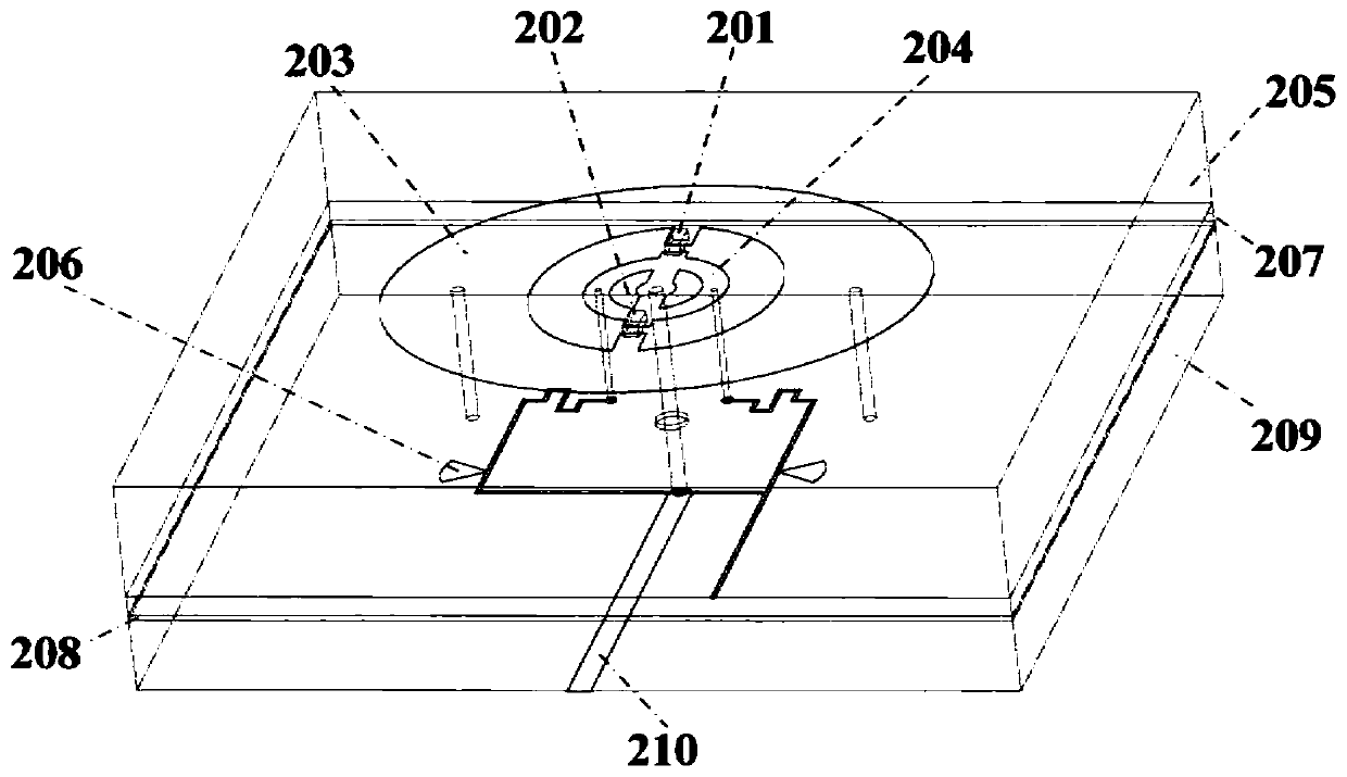
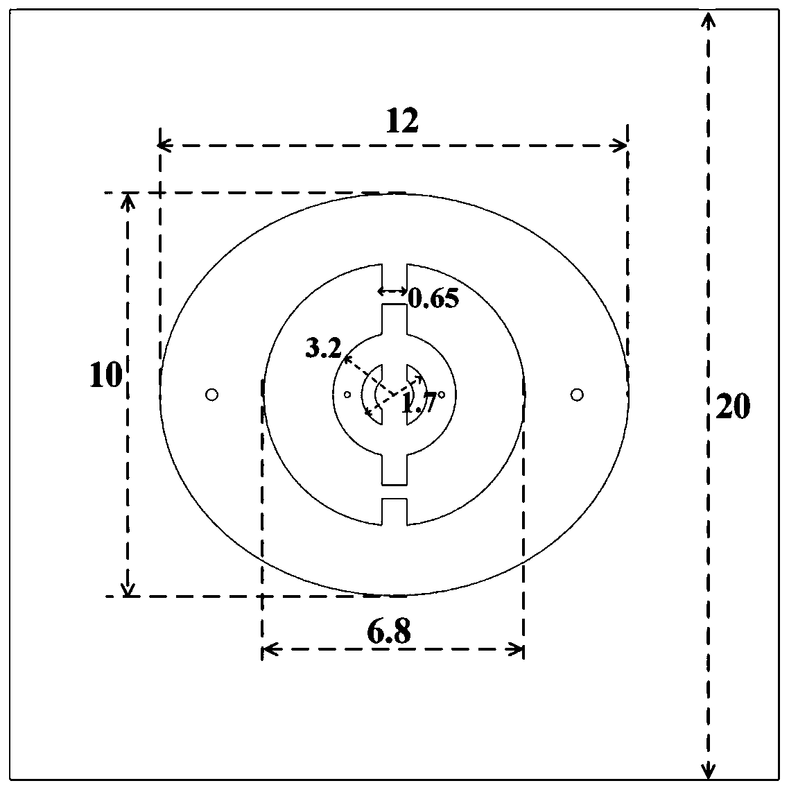
[0038] Also refer to Figure 2 to Figure 5 .

[0039] Please refer to Fig. 2 for the structure schematic diagram and dimension drawing of the new direct radiation type one-bit digital coded antenna unit 2, as can be seen, it is characterized in that two PIN diodes are integrated in the unit structure, and the unit structure includes 4 alternately arranged Layer metal structure and 3 dielectric layers, its composition includes: PIN diode I 201, PIN diode II 202, outer radiation metal patch 203, inner radiation metal patch 204, upper dielectric substrate 205, bias control layer 206, semi-cured Adhesive sheet 207 , metal floor 208 , lower dielectric substrate 209 , and feed network layer 210 . Among them, the PIN diode I 201 and the PIN diode II 202 are located at the junction of the outer radiating metal patch 203 and the inner radiating metal patch 204; the relative permittivity and thickness of ...

Embodiment 2

[0044] Embodiment 2: Novel digital phased array antenna made of coded antenna unit

[0045] see also Figure 6 to Figure 8 .

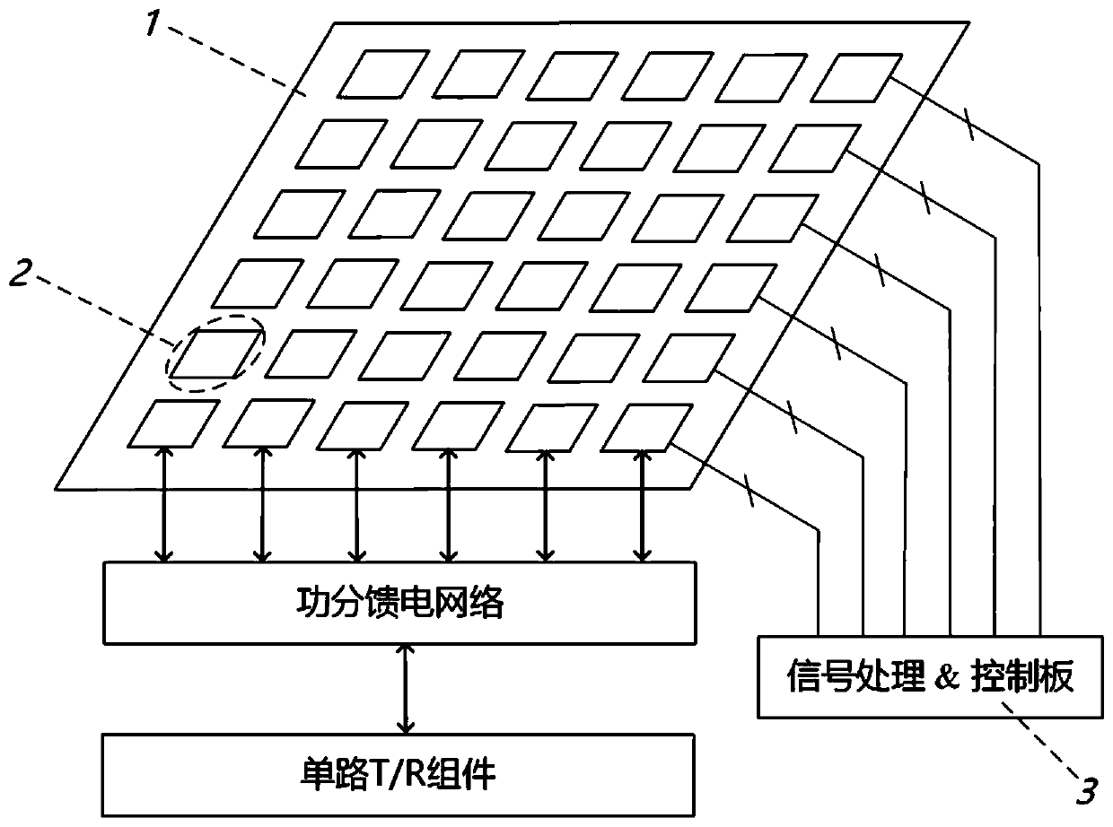
[0046] Further, the direct radiation type one-bit digital coded antenna unit is arranged in an array according to the periodic square grid distribution, and fed through the power dividing network, which constitutes a new type of digitally coded phased array antenna. In this embodiment A digital phased array antenna with 16×16 array elements is constructed. The overall size of the array is 320mm×320mm×2.238mm. The detailed structure can be found in Image 6 .

[0047] The power distribution network used for unit feed in the phased array system can use microstrip power distribution network, waveguide power distribution network, substrate integrated waveguide (SIW) power distribution network, gap waveguide power distribution network (GWG) and so on. kind of form. In this embodiment, the unequal series-parallel hybrid feeding network is preferably used...

Embodiment 3

[0049] Embodiment 3: adopting novel digital phased array antenna to realize beam scanning

[0050] In this embodiment, scanning beams with different directions are generated by controlling the code distribution of the units on the array. For details, please refer to Figure 9 to Figure 14 .

[0051] First, control the code distribution of the units on the one-bit digital phased array antenna, and use the equal-phase surface synthesis method to perform code quantization and optimization, so that the beam pointing is (0°,0°), at this time, the code distribution of each unit on the array is as follows Figure 9 As shown, the obtained 3D beam pattern and its The sections above are as Figure 10 and Figure 11 It can be seen that the maximum gain of the array antenna is 23.7dB at this time, and the sidelobe level is below -16dB.

[0052] Further verify the effect of beam scanning, control the code distribution of the units on the one-bit digital phased array antenna, and use...


PUM

PropertyMeasurementUnit
Thicknessaaaaaaaaaa

Abstract

The invention provides a one-bit digital coding antenna unit and a digital phase array antenna system. A PIN diode is integrated on a radiating patch of a direct radiation type digital coding antennaunit provided by the invention; by applying different biases to the PIN diode, radiation beams of the antenna unit take on two phase positions, that is, 0 degree and 180 degrees, which correspond to numerical codes "0" and "1", respectively. By arranging each unit periodically to form an array and feeding through a power division network, a novel phase array antenna is formed; and as code distribution of units on the array is controlled through the optimization algorithm, scanning beams in different orientations or shaped-beams in different shapes can be generated. Compared with the traditional phase array antenna, the digital phase array antenna system reduces system cost and complexity; and compared with digital coding super-surface based phase array antenna, the digital phase array antenna system reduces the profile and volume of the system, avoids energy leakage caused by spacial irradiation feed and improves overall efficiency of the antenna.

Description

technical field [0001] The invention relates to the technical field of microwave antennas and novel phased array systems, in particular to a one-bit digital coded antenna unit and a novel digital phased array antenna system composed of it. Background technique [0002] The phased array antenna replaces mechanical scanning with electronically controlled scanning, so that the antenna has the ability to quickly scan the beam tracking, the ability to change the beam shape rapidly, the ability to combine spatial power, and excellent spatial orientation and spatial filtering capabilities. In the traditional phased array antenna system, in order to realize the dynamic scanning of the beam and other functions, a large number of phase shifters and corresponding complex control networks need to be used in the T / R component, and the phase of the antenna unit is changed by the phase shifter, and then Controlling the antenna pattern so that its beam points to a specific target is extreme...

Claims


Application Information

Patent Timeline
IPC IPC(8): H01Q1/38H01Q1/48H01Q1/50H01Q3/34H01Q21/00H01Q21/06H01Q21/29
CPCH01Q1/38H01Q1/48H01Q1/50H01Q3/34H01Q21/0006H01Q21/061H01Q21/293
Inventor 白旭东孔凡伟钱婧怡孙朦朦吕艳亭宋云卓徐晟阳贺冲
Owner SHANGHAI AEROSPACE ELECTRONICS CO LTD
Why Eureka
Try Eureka