Planar microwave resonant antenna with dual frequency points and high radiation efficiency

A microwave resonance and high radiation technology, applied in the field of radio frequency microwave, can solve the problems of difficult manufacturing, single application range, complex structure, etc., to reduce the occupied space, achieve dual-frequency compatibility, and reduce the length.

Active Publication Date: 2020-02-14
ZHONGBEI UNIV
View PDF10 Cites 5 Cited by
  • Summary
  • Abstract
  • Description
  • Claims
  • Application Information

AI Technical Summary

Problems solved by technology

Today's multi-frequency point antenna design generally has a complex structure. Some of them introduce spurious resonances of different resonance frequencies, and some use multiple coupling feeds to form multi-frequency points.
The design of multi-layer stacking and three-dimensional design is difficult to manufacture, and the shape and volume are limited by the application environment
[0005] Existing multi-frequency antennas have a clear purpose in design, resulting in a relatively single application range. They are mostly used in mobile communications, and there are even multi-frequency antennas with eight operating frequency points, but they cannot be applied to realize multiple pulse sequences. The NMR experiment
The operating frequency points are only distributed in the low frequency band, or are only distributed in the high frequency band, which cannot meet the requirements for the resonance frequency of nuclear magnetic resonance related experiments. Therefore, it is necessary to further improve the performance of the antenna to make it more flexible for different operating frequency bands. experiment

Method used


Image

  • Planar microwave resonant antenna with dual frequency points and high radiation efficiency
  • Planar microwave resonant antenna with dual frequency points and high radiation efficiency
  • Planar microwave resonant antenna with dual frequency points and high radiation efficiency

Examples


Embodiment Construction

[0029] Specific embodiments of the present invention will be described in detail below in conjunction with the accompanying drawings.

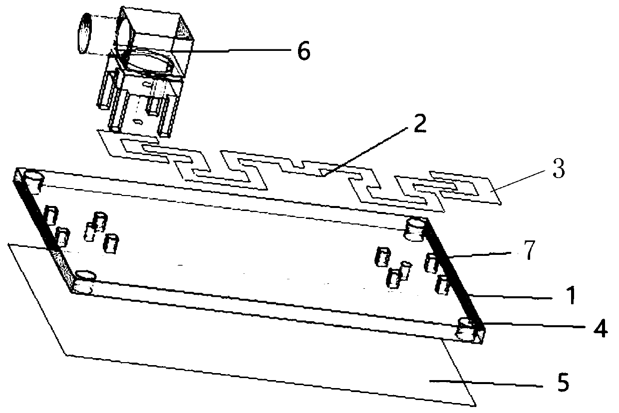
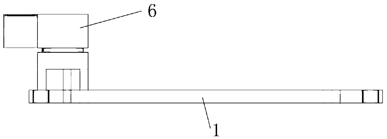
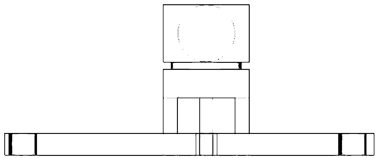
[0030] A miniaturized planar dual-frequency point microwave resonant antenna with high radiation efficiency, such as figure 1 As shown, it includes a dielectric substrate 1 , a ground radiation patch 5 , a feed port 3 and a feeder 2 made of metal foil. The bottom surface of the dielectric substrate 1 is provided with a ground radiation patch 5, and the upper surface of the dielectric substrate 1 is provided with a metal foil feeder 2 and a feeder port 3, and the two feeder ports 3 are located at both ends of the metal foil feeder 2; the dielectric substrate 1 There is a connector installation hole 7 at the feed port 3 on the top, and an SMA connector 6 is installed in the connector installation hole 7. The SMA connector 6 connects the feed port 3 and the ground radiation patch 5, and the four corners of the dielectric substrate 1 have platform...


PUM


Abstract

The invention discloses a novel planar microwave resonant antenna with dual frequency points and high radiation efficiency, including a rectangular dielectric substrate, a grounding radiation patch onthe bottom surface of the substrate and a rectangular broken line symmetrically concave metal foil feeder line arranged on the upper surface of the dielectric substrate. A SMA joint is used to directly weld the inner part onto the feeder line and connect the grounding radiation patch. The simulation design is carried out by means of electromagnetic simulation software ANSYS HFSS, real-time simulation is carried out by changing the shape and size of a feed antenna, multi-parameter simulation data and simulation diagrams are combined for calculation, the structure, material and process of the antenna are optimized, and the reliability of a simulation result is confirmed. The effective radiation resistance of the antenna is increased, the generation of high-order modes is reduced, the radiation efficiency of the antenna is improved, the overall effect of the antenna system is improved, the requirements of double frequency points and high radiation efficiency are realized on the same substrate and the same plane, and the application of double frequency points is realized.

Description

technical field [0001] The invention relates to the field of radio frequency microwaves, in particular to a planar dual-frequency point microwave resonant antenna with high radiation efficiency, which is applied to research in the field of nuclear magnetic resonance. Background technique [0002] With the increasing progress of nuclear magnetic resonance technology, as a non-destructive measurement technology, it has been valued due to its high resolution, rapidity, accuracy and rich information in the analysis of substances, and it provides an important analytical measurement for multidisciplinary research. technical support. By applying radio-frequency microwaves, when the frequency matches the Larmor precession of the spins, a resonance is generated. In its experiments and applications, it is necessary to use antennas with higher radiation efficiency to provide a microwave environment for related pulse modulation experiments. Nowadays, the most widely used antenna in th...

Claims


Application Information

Patent Timeline
Patent Type & Authority Applications(China)
IPC IPC(8): H01Q1/38H01Q1/48H01Q1/50H01Q5/20H01Q9/04
CPCH01Q1/38H01Q1/48H01Q1/50H01Q9/04H01Q5/20
Inventor 刘俊李中豪唐军郭浩陈艺萱马宗敏温焕飞
Owner ZHONGBEI UNIV
Why Eureka
Try Eureka