Motion control system of arc spray gun
A technology of motion control system and arc spray gun, which is applied in the general control system, control/regulation system, computer control, etc., can solve the problems of poor readability of manual writing, damage to the billet surface, loss of real-time performance, etc., and achieve high efficiency of spray marking , increase the arc temperature, enhance the effect of atomization effect
- Summary
- Abstract
- Description
- Claims
- Application Information
AI Technical Summary
Problems solved by technology
Method used
Image
Examples
Embodiment 1
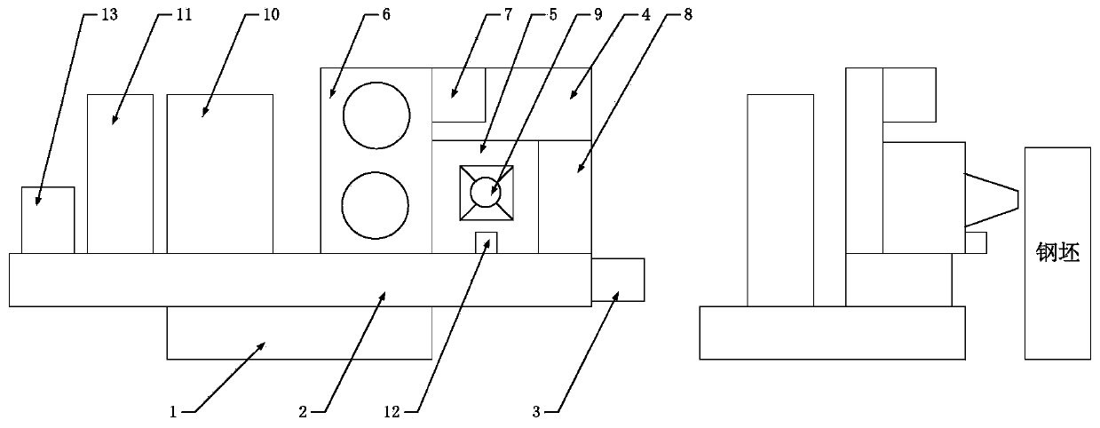
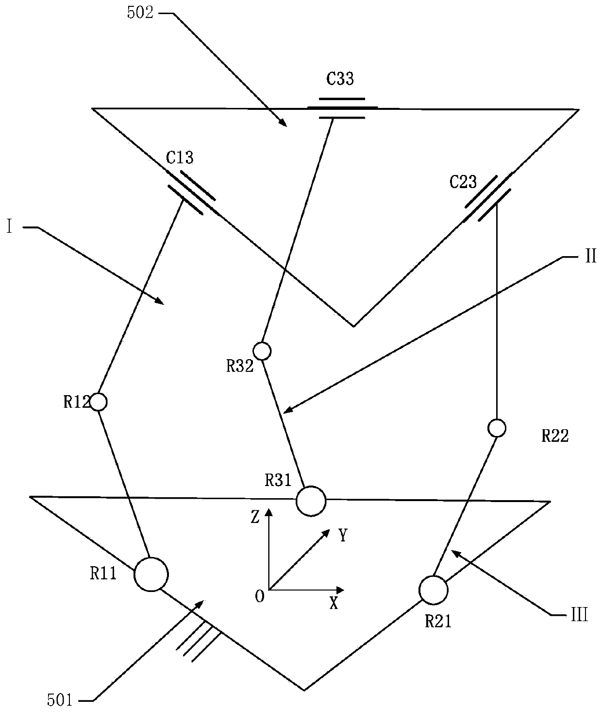
[0022] A motion control system for an arc spray gun, such as figure 1 As shown, the motion control system includes: a basic platform, a traverse module, a traverse motor, a support frame, a parallel motion platform, a wire feeding mechanism, a blower, a descaler, an arc spray gun, a power supply system, and a compressed air supply system , position sensor, computer. The traverse module is fixedly connected to the upper front end of the foundation platform, the traverse motor is fixed to one side of the traverse module, and is used to drive the slide table of the traverse module to move laterally, and the support frame is fixed Connected directly above the slide table of the traverse module, the parallel motion platform, wire feeding mechanism, blower, and descaler are all fixedly connected to the support frame, and the parallel motion platform is located in the middle of the support frame. The wire feeding mechanism is located on the left side of the parallel motion platform,...
Embodiment 2
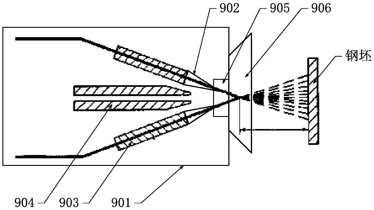
[0026] An arc spray gun for arc spray marking systems such as image 3 As shown, it includes gun body, contact tip, wire feeding pipe, air atomizing nozzle, air cap, arc shield, etc. The gun body is the main body of the arc spray gun, fixed on the center of the moving platform of the parallel motion platform; the wire feeding pipeline is symmetrically distributed on both sides of the central axis inside the gun body, and is used to provide guidance to the metal wire; the conductive The nozzle is located at the front end of the wire feeding pipeline, and is used to form an arc between two metal wires. The high temperature of the arc will melt the metal wires to form molten droplets; the air atomizing nozzle is located on the central axis of the gun body. At the rear of the contact tip, the compressed air is accelerated by the air atomizing nozzle to form a high-speed atomizing air with great kinetic energy, which completes the atomization of the liquid droplets in the molten st...
Embodiment 3
[0028] A motion control system for an arc spray gun, its overall architecture is as follows Figure 4As shown, the computer is electrically connected to the traverse motor, servo motor M1, servo motor M2, servo motor M3, arc spray gun, power supply system, compressed air supply system, descaler, and position sensor, and the computer is electrically connected to the traverse motor. The motor is electrically connected to control the lateral movement of the traverse module; the computer is electrically connected to the servo motor M1, servo motor M2, and servo motor M3 to drive the corresponding rotating pairs R11, R21, and R31 to operate in parallel, thereby controlling The displacement and speed of the parallel motion platform in three directions; the computer is electrically connected with the power supply system, and the power supply system is electrically connected with the arc spray gun for controlling the voltage supply of the arc spray gun; the computer is electrically con...
PUM
 Abstract
Description
Claims
Application Information
 - R&D
- Intellectual Property
- Life Sciences
- Materials
- Tech Scout
- Unparalleled Data Quality
- Higher Quality Content
- 60% Fewer Hallucinations
Browse by: Latest US Patents, China's latest patents, Technical Efficacy Thesaurus, Application Domain, Technology Topic, Popular Technical Reports.
© 2025 PatSnap. All rights reserved.Legal|Privacy policy|Modern Slavery Act Transparency Statement|Sitemap|About US| Contact US: help@patsnap.com


