
Electromagnetic heating rotary kiln with function of controlling reducing atmosphere

A rotary kiln and electromagnetic technology, applied in the field of rotary kiln, can solve the problems of increased cost of transmission motor and supporting device, easy agglomeration on the surface, heavy weight of rotary kiln, etc., and achieves improved service life, reduced equipment cost, installation and maintenance The effect of reducing the maintenance workload

Active Publication Date: 2020-02-25
上海江竑环保科技有限公司
View PDF8 Cites 2 Cited by
  • Summary
  • Abstract
  • Description
  • Claims
  • Application Information

AI Technical Summary

Problems solved by technology

The weight of this type of rotary kiln is relatively large, up to 200-600 tons, and the cost of the supporting drive motor and supporting device also increases accordingly. The cost of a complete set of equipment and systems is as high as hundreds of millions of yuan
At the same time, because refractory bricks have been working in a high temperature and corrosive environment exceeding 1000-1200 °C for a long time, after continuous use, most of the refractory bricks are prone to agglomeration on the surface after 3-6 months, which seriously affects the metallurgical dust. The separation and recovery process often requires re-stacking of refractory bricks to ensure the normal operation of the rotary kiln. This kind of maintenance time will take up to half a month or even one month. The shutdown maintenance will cause huge direct economic losses to users.

Method used


Image

  • Electromagnetic heating rotary kiln with function of controlling reducing atmosphere
  • Electromagnetic heating rotary kiln with function of controlling reducing atmosphere
  • Electromagnetic heating rotary kiln with function of controlling reducing atmosphere

Examples


Embodiment 1

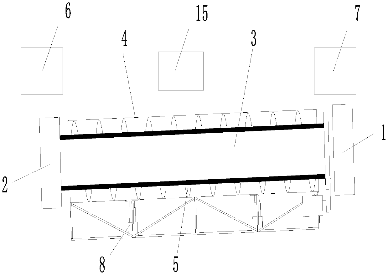
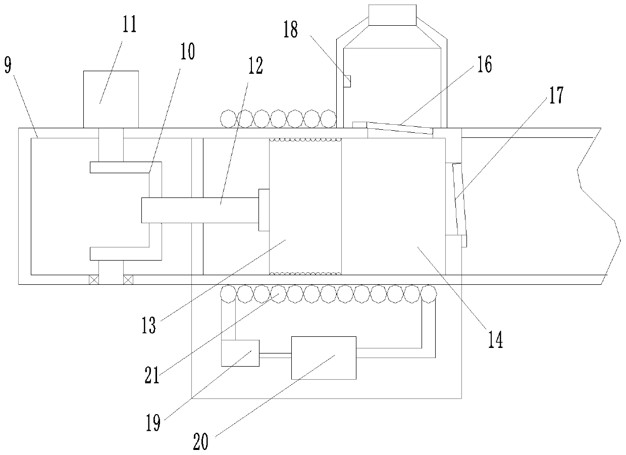
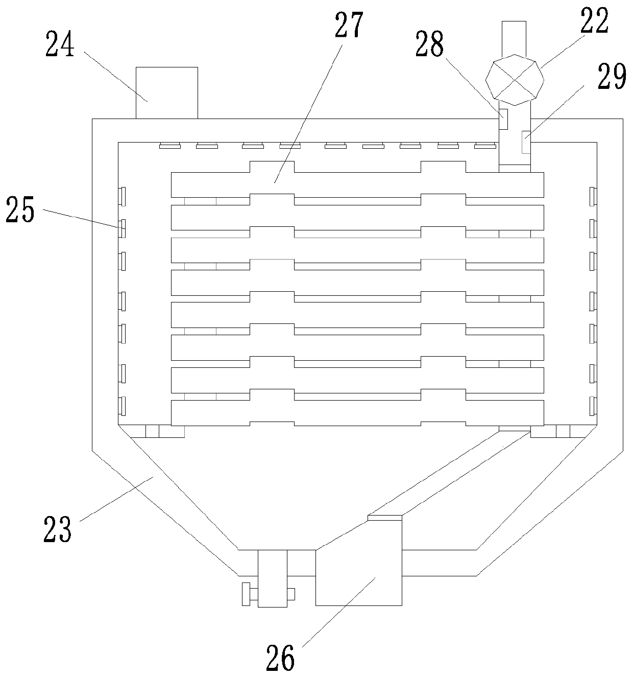
[0029] Such as figure 1 with Figure 5 As shown, an electromagnetic heating rotary kiln with the function of controlling the reducing atmosphere has a feeding part 1, a main kiln part and a discharging part 2. The feeding part 1 and the discharging part 2 are respectively sealed and connected to the ports of the corresponding main kiln part The main kiln section includes a high-temperature oxidation resistant movement 3, a back-end gas transmission device 6, a front-end exhaust emission device 7 and a control system 15. The movement 3 is made of Cr-Ni-Mo-W-Fe-Si alloy series material The movement 3 is arranged low to the left and high to the right. A protective cover 4 is provided on the outside of the movement 3. A gap is reserved between the movement 3 and the protective cover 4, and an electromagnetic induction heating structure 5 is provided in the gap, which is heated by electromagnetic induction Structure 5 generates eddy current heating on the conductive movement 3 and t...

Embodiment 2

[0031] The difference from Embodiment 1 is that the bottom of the protective cover 4 is provided with a height adjustment device 8, such as a hydraulic lifting device, and the movement 3 and the protective cover 4 are adjusted by the height adjustment device 8 at an angle of 0.5°-8°. The control system 15 is used to control the reducing gas delivery volume and the exhaust gas discharge volume, and the height adjustment device 8 is used to adjust the inclination angle of the movement 3 to further ensure the flow speed of the reducing gas inside the movement 3, so that the chlorination reduction reaction of the material It is carried out in a controllable reduction range, which greatly improves the efficiency of the reaction and the speed of sublimation and separation.

[0032] In this embodiment, the solution is further optimized, the movement 3 is provided with six transversely, and two adjacent movement 3 are detachably connected by flanges, and the electromagnetic induction heat...

Embodiment 3

[0034] Further optimized on the basis of Example 1, the raw materials of movement 3 specifically include components by weight: 12 parts of Cr, 56 parts of Ni, 16 parts of Mo, 8 parts of W, 6 parts of Fe, 1.0 Parts of mixed rare earth RE and 1.0 part of Si, wherein the mixed rare earth RE contains the following components by weight percentage: 6.5% Ce, 8.6% Nd, 5.4% Pm, 6.2% Sm, the balance is La, S1, movement base Material production: All the movement raw materials are mixed in proportion and then smelted, and casted by centrifugal casting method, followed by solution heat treatment: 1180℃ for 4h, and then water quenched, so that the structure becomes a single-phase solid solution to achieve uniformity of the structure, and then natural Cool to room temperature to obtain the core substrate, and then mechanically process the inner surface of the core substrate to smooth; S2, cladding anti-element depletion barrier layer coating: mix the anti-element depletion coating powder unifo...


PUM


Abstract

The invention discloses an electromagnetic heating rotary kiln with the function of controlling reducing atmosphere, and belongs to the field of rotary kilns. The electromagnetic heating rotary kiln comprises a feeding portion, a main kiln portion and a discharging portion. The feeding portion and the discharging portion are in sealed connection to a front port and a rear port of the correspondingmain kiln portion correspondingly. The main kiln portion comprises a core resisting to high-temperature oxidization, a rear-end gas conveying device and a front-end tail gas exhaust device. The coreis made of a Cr-Ni-Mo-W-Fe-Si alloy material. The left portion of the core is lower than the right portion of the core, and a protection cover is arranged on the outer side of the core. A gap is reserved between the core and the protection cover, and an electromagnetic induction heating structure is arranged in the gap. The electromagnetic induction heating structure generates vortexes on the electric conduction core to emit heat, the heat is transmitted to materials turning over in the core, reduction gas is controllably input from the left end of the core through the rear-end gas conveying device under the action of a control system, and then tail gas generated after reacting in the whole core is controllably exhausted from the rear end of the core through the front-end tail gas exhaustdevice under the action of the control system.

Description

Technical field [0001] The invention belongs to the technical field of a rotary kiln, and specifically relates to an electromagnetic heating rotary kiln that realizes real-time control of the reducing atmosphere in the kiln. Background technique [0002] The separation and recycling of heavy metal elements and harmful elements in metallurgical dust and mud are usually treated by rotary kilns. The metallurgical dust and sludge are roasted in the rotary kiln, and a high-temperature chlorination reduction reaction occurs, so that the heavy metal elements and harmful elements in it react to form chlorides or elemental gases that are easy to sublime, which are separated from the metallurgical dust and sludge body, and discharged into the tail gas for separation and recovery. . Most of the existing rotary kilns use ordinary steel materials as the outer shell. Refractory bricks are piled on the inner wall of the outer shell to form the kiln body. The metallurgical dust and mud complete...

Claims


Application Information

Patent Timeline
Patent Type & Authority Applications(China)
IPC IPC(8): F27B7/06F27B7/08F27B7/20F27B7/22F27B7/28F27B7/34F27B7/36F27B7/38F27B7/42
CPCF27B7/06F27B7/08F27B7/20F27B7/22F27B7/28F27B7/34F27B7/36F27B7/38F27B7/42
Inventor 欧钱江强雄召王端祥吴家骥成振宏毛协民
Owner 上海江竑环保科技有限公司
Learn More