
A 3D printing method for laser selective solidification of metal

A 3D printing and laser selection technology, which is applied in the direction of process efficiency improvement, additive manufacturing, additive processing, etc., can solve the problems of low printing efficiency and low forming precision, and achieve fast forming speed, high forming precision and high strength of parts Effect

Active Publication Date: 2020-10-13
UNIV OF SCI & TECH BEIJING
View PDF6 Cites 0 Cited by
  • Summary
  • Abstract
  • Description
  • Claims
  • Application Information

AI Technical Summary

Problems solved by technology

[0007] The invention provides a 3D printing method for laser selective solidification of metal, which solves the problems of low forming precision and low printing efficiency after printing and extrusion of metal paste

Method used


Image

  • A 3D printing method for laser selective solidification of metal

Examples


Embodiment example 1

[0032] The steps of preparing iron-based alloy parts are as follows:

[0033] (1) Equipped with a photosensitive solvent: acryloylmorpholine (ACMO, with a purity of 98%) and 2,4,6-trimethylbenzoyl-diphenyl (Omnirad TPO) were prepared according to a mass ratio of 95:5 For comparison, add the two together and stir evenly with a glass rod to fully dissolve TPO into ACMO, prepare it as a photosensitive solvent and pour it into an aluminum bottle for later use;

[0034] (2) Preparation of photosensitive slurry: Measure 7ml of photosensitive solvent, place it under a digital display electric stirrer to stir and mix at a speed of 800rpm, weigh 100g of iron-based alloy 10V powder (D 50 = 30 μm), gradually add the powder into the photosensitive solvent, increase the rotation speed to 1600 rpm and stir for 30 minutes after the powder is completely added, to obtain a uniform photosensitive slurry without aggregates, and the solid phase volume fraction is 65.5%. Adding 3wt.% oleic acid a...

Embodiment example 2

[0040] The steps of preparing titanium alloy parts are as follows:

[0041] (1) Pour 15g of acryloylmorpholine (ACMO, with a purity of 98%) into a beaker, then weigh 0.75g of 2,4,6-trimethylbenzoyl-diphenyl (Omnirad TPO) and pour Pour into a beaker and stir until fully dissolved for later use;

[0042] (2) Weigh a certain amount of titanium alloy TC4 powder (particle size 50 μm), add the prepared photosensitive solvent to make its solid content 63vol.%, and add 0.5wt.% stearic acid to improve fluidity, pour Mixing is carried out in the mixing tank of the vacuum planetary ball mill, the ball to material ratio is 1:1, the ball milling speed is 100rpm, the ball milling time is 30min, and the slurry after ball milling is taken out for use;

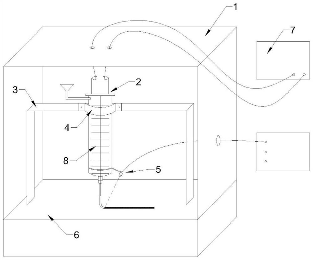
[0043] (3) Design the three-dimensional structure of the printed part, slice it in the computer slicing software, and import the sliced ​​data into the attached figure 1 In the 3D printing control device (1) shown in;

[0044] (4) Inject th...


PUM

PropertyMeasurementUnit
particle diameteraaaaaaaaaa
thicknessaaaaaaaaaa

Abstract

The invention provides a 3D printing method for selective laser solidification of metal, which belongs to the technical field of 3D printing forming. Firstly, the metal powder is mixed with the liquid photosensitive resin, and then a dispersant is added to the slurry to adjust the rheological properties of the slurry to prepare a photosensitive slurry with an appropriate solid phase volume fraction and good rheological properties. The 3D printing device is used to extrude the slurry from a nozzle with a certain diameter; at the same time, in the process of slurry streamline extrusion, dispersion and accumulation, a fine laser beam selection is used to scan synchronously on the slurry streamline plane, making it Partial rapid solidification forming, reciprocating, so that the forming of metal parts of a certain shape can be realized. The invention can directly form high-precision metal parts, has high forming speed, high part strength, uniform density, low cost and no special requirements on working environment.

Description

technical field [0001] The invention belongs to the field of 3D printing forming technology, and provides a 3D printing method for laser selective solidification of metal. Background technique [0002] 3D printing technology is a technology that produces three-dimensional entities directly from digital models through material accumulation, and is considered to have great potential in the direct forming of metal parts of arbitrary complex shapes. At present, the mainstream 3D printing technology uses high-energy beams such as laser beams and electron beams to heat and melt pre-laid metal powders, and build up three-dimensional parts layer by layer. Metal and alloy parts such as titanium and titanium alloys, superalloys, and magnesium-aluminum alloys have been realized. direct manufacturing. However, the printing powder must meet the requirements of high sphericity, good fluidity, high bulk density, fine particle size and narrow particle size distribution. However, many mate...

Claims


Application Information

Patent Timeline
Patent Type & Authority Patents(China)
IPC IPC(8): B22F3/22B22F3/105B22F3/10C22C14/00B33Y10/00B33Y50/02
CPCB22F3/227B22F3/1021B22F3/1007C22C14/00B33Y10/00B33Y50/02B22F10/00B22F12/41B22F10/36B22F10/12B22F10/68Y02P10/25
Inventor 杨芳汪豪杰郭志猛秦乾陈存广路新邵艳茹孙海霞
Owner UNIV OF SCI & TECH BEIJING
Learn More