

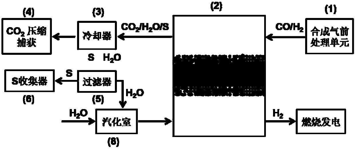
Novel IGCC system and method for realizing CO2 capture before combustion by using mixed conductor oxygen permeation membrane reactor
A mixed conductor, membrane reactor technology, applied in chemical instruments and methods, hydrogen production, carbon compounds, etc., can solve the problem of high energy consumption
- Summary
- Abstract
- Description
- Claims
- Application Information
AI Technical Summary
Problems solved by technology
Method used
Image

Examples
Embodiment 1
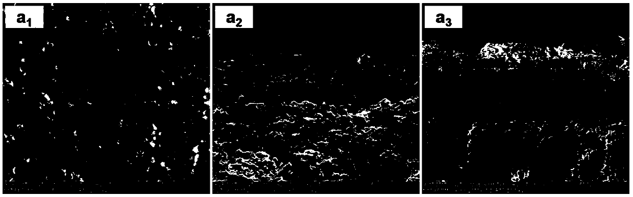
[0056] 75wt.% Ce 0.85 SM 0.15 o 2-δ -25wt.%Sm 0.6 Sr 0.4 Cr 0.3 Fe 0.7 o 3-δ (LL Cai, etal.J.Membr.Sci.2016,520,607–615.) As a membrane material in a membrane reactor, a sheet-shaped supporting membrane is prepared, and the thickness of the dense layer is ~36μm, such as figure 2 . Brushing Ni / Ce on membrane dense layer (syngas side) 0.85 SM 0.15 o 1.925 (Ni / SDC) catalyst, water side impregnated Ni / SDC catalyst. The membrane is sealed in the membrane reactor with a silver ring. After slowly cooling down to 900°C, the flow rate of the water side of the membrane is 180mL min -1 H 2 O, the synthesis gas side uses a flow rate of 100mL min -1 Syngas (50% CO, 49.94% H 2 , 600ppmH 2 S). The hydrogen separation rate is 14.6mL cm -2 min -1 , The CO conversion rate was 8.3%. After a 100h stability test, the hydrogen separation performance did not attenuate, and the CO conversion rate remained constant.
Embodiment 2
[0058] SrFe 0.9 Ta 0.1 o 3-δ (WQ Jin, et al. J. Mater. Chem. A, 2015, 3, 22564–22573.) The membrane material was pressed into a sheet-like membrane with a thickness of ~0.5 mm. The Ru / SDC catalyst was brush-coated on both sides of the membrane, and the membrane was sealed in the membrane reactor with a silver ring. After slowly cooling down to 900°C, the flow rate of the water side of the membrane is 180mL min -1 H 2 O, the synthesis gas side uses a flow rate of 100mLmin -1 Syngas (50% CO, 49.96% H 2 , 400ppm H 2 S). The hydrogen separation rate is 8.2mL cm -2 min -1 , The CO conversion rate was 6.3%. After a 100h stability test, the hydrogen separation performance did not attenuate, and the CO conversion rate remained constant.
Embodiment 3
[0060] 75wt.% Ce 0.85 SM 0.15 o 2-δ -25wt.%Sm 0.6 Sr 0.4 al 0.3 Fe 0.7 o 3-δ (XF Zhu, et al. Solid State Ionics 2013, 253, 57–63.) The membrane material was prepared as a tubular membrane, and the thickness of the outer dense layer was ~40 μm. The Ru / SDC catalyst is brushed on the outside of the membrane, and the Ru / SDC catalyst is impregnated on the inside. The membrane is sealed in the membrane reactor with a silver ring. After slowly cooling down to 800°C, the inner side of the membrane (water side) was fed with a flow rate of 180mL min -1 H 2 O, outside (syngas side) with a flow rate of 100mL min -1 Syngas (50% CO, 49.96% H 2 , 400ppm H 2 S). The hydrogen separation rate is 11.4mL cm -2 min -1 , The CO conversion rate was 7.5%, and the stability test was carried out for 100 hours. The hydrogen separation performance did not decay, and the CO conversion rate remained constant.
PUM
| Property | Measurement | Unit |
|---|---|---|
| thickness | aaaaa | aaaaa |
| thickness | aaaaa | aaaaa |
| thickness | aaaaa | aaaaa |
Abstract
Description
Claims
Application Information