Junction box for photovoltaic module

A photovoltaic module and junction box technology, applied in the field of solar photovoltaic power generation, can solve the problems of reducing power generation efficiency per unit space area, cumbersome and complicated process, unfavorable component cost, etc., to achieve increased heat dissipation capacity, convenient processing technology, and strong over-current capability Effect

Pending Publication Date: 2020-02-28
QC SOLAR SUZHOU CORP
View PDF0 Cites 0 Cited by
  • Summary
  • Abstract
  • Description
  • Claims
  • Application Information

AI Technical Summary

Problems solved by technology

At present, the junction boxes for photovoltaic modules are generally designed for straight-line or oblique outlets, which is more suitable for ordinary photovoltaic modules, but for new high-efficiency double-glass modules, double-sided power generation There are many problems, because these types of photovoltaic modules are greatly affected by the area covered by the junction box. Therefore, small-volume split junction boxes are generally used, and the junction box is also installed as close to the edge of the module as possible. Minimize the impact on the power generation performance of the components (the junction box blocking the power generation surface of the battery will cause local "hot spots" of the components). Cables are bent for wiring. In this way, there must be space for cables to be bent and routed on the module. The non-power generation area occupied by the edge of the module will be relatively large, which is not conducive to the reduction of the cost of the module, and also reduces the cost per unit space area. Power generation efficiency; moreover, because the cables need to be bent and wired, the process of component installation and construction is more cumbersome and complicated, and the work efficiency is low

Method used


Image

  • Junction box for photovoltaic module
  • Junction box for photovoltaic module
  • Junction box for photovoltaic module

Examples


Embodiment Construction

[0033] The structure, features and advantages of the present invention are described in detail below in conjunction with the accompanying drawings and specific embodiments.

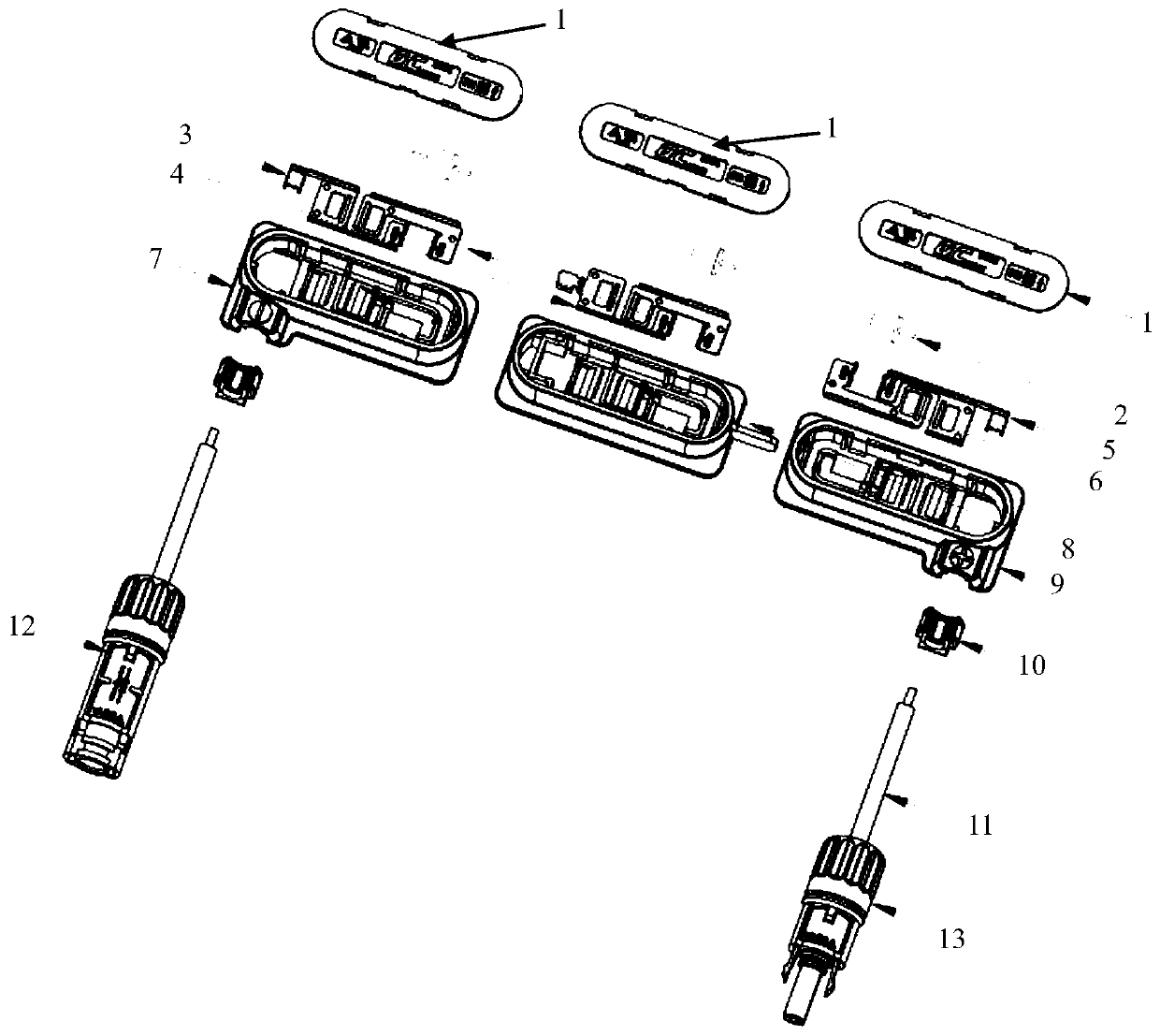
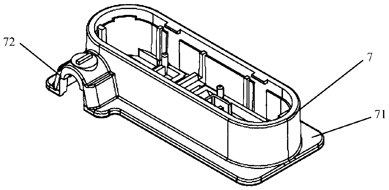
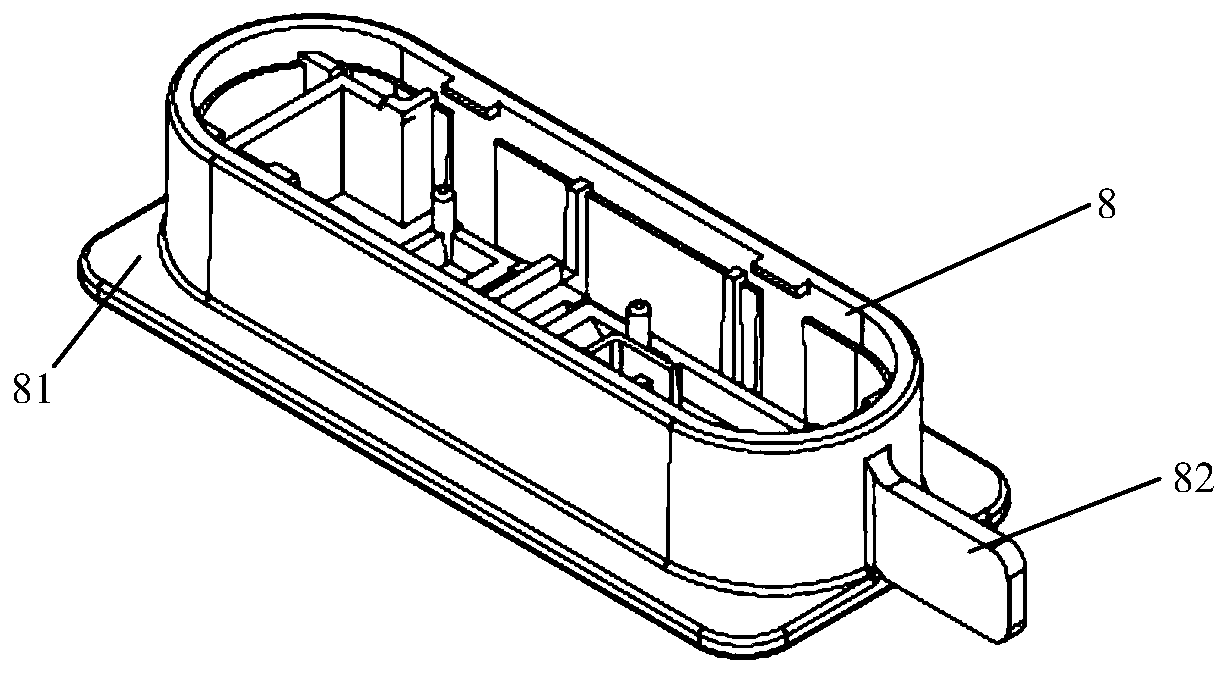
[0034] combined reference Figure 1 to Figure 12 As shown, the photovoltaic module junction box of the present invention includes a left junction box, a middle junction box and a right junction box, the left junction box includes a box cover 1 and a box body 7, and the middle junction box includes a box cover 1 and a box body 7. Box body 8, the right junction box includes a box cover 1 and a box body 9; the bottom length direction of the left junction box body 7 is provided with skirt structures 71 on the upper and lower sides, and the box body 7 is integrally formed with wired The cable outlet part 72, the direction of the cable outlet of the outlet part 72 is perpendicular to the length direction of the box body, the box body 7 includes the first connection terminal 3 and the fourth connection terminal ...


PUM


Abstract

The invention provides a junction box for a photovoltaic module. The junction box comprises a left junction box, a middle junction box and a right junction box which each comprises a box cover and a box body. Cable outlet parts are integrally formed on the box bodies of the left junction box and the right junction box, and the directions of cable outlets are perpendicular to the length directionsof the box bodies. Each junction box comprises two wiring terminals of which the main bodies are of a concave structure. In the box body of each junction box, two connecting terminals are of a spacedwedge-joint structure similar to that of opposite insertion of fingers of two hands. According to the invention, the wire outlet mode of the left and right junction boxes is optimized to be close to or equal to 90 degrees, so that the distance from a module frame to the wire outlet end of the junction box is reduced, convenience is provided for module processing, the cost is saved, the effective power generation area of the assembly is increased, and the power generation efficiency is improved. Axial diodes are used and form an integral structure with the wiring terminals through electric resistance welding, so that the integral current passing capacity is improved, the heat dissipation capacity of the diodes is greatly improved, and the high current passing capacity is stronger. The junction box is applicable to high-power modules such as imbricate modules, double-sided modules and double-glazed modules.

Description

technical field [0001] The invention relates to the technical field of solar photovoltaic power generation, in particular to a junction box for high-efficiency power generation photovoltaic components such as new shingled photovoltaic components, double-glass photovoltaic components, and double-sided photovoltaic components. Background technique [0002] In response to the increasingly serious environmental pollution problems caused by the use of traditional fossil energy, the green and renewable energy industry has developed rapidly in recent years. The solar cell power generation technology that uses the photovoltaic effect to generate electricity is an important green energy technology. Solar cells are made of materials that can produce photovoltaic effects, such as silicon, gallium arsenide, indium selenide copper and other materials, which can convert light energy into electrical energy. At present, photovoltaic modules composed of multiple solar cells are widely used a...

Claims


Application Information

Patent Timeline
Patent Type & Authority Applications(China)
IPC IPC(8): H02S40/34
CPCH02S40/34H02S40/345Y02E10/50
Inventor 段正刚
Owner QC SOLAR SUZHOU CORP
Why Eureka
Try Eureka