Heat exchange device and garbage disposal system with the same

A technology for heat exchange devices and heat exchange walls, applied in indirect heat exchangers, steam generation methods using heat carriers, lighting and heating equipment, etc., can solve the problem of temperature rise of heat exchange walls, corrosion of heat exchange walls, etc. problems, to achieve the effect of low wall temperature, low corrosion rate and large thermal resistance

Pending Publication Date: 2020-03-20
CHINA ENFI ENGINEERING CORPORATION
View PDF0 Cites 0 Cited by
  • Summary
  • Abstract
  • Description
  • Claims
  • Application Information

AI Technical Summary

Problems solved by technology

The heat exchange device of the present application can increase the temperature of the low-temperature medium while avoiding the obvious increase of the temperature of the heat-exchange wall surface in contact with the high-temperature medium, and solves the existing problem of corrosion of the heat-exchange wall surface in contact with the high-temperature medium caused by increasing the parameters of the low-temperature medium At the same time, it does not need to use expensive high-alloy corrosion-resistant steel for the heat exchange wall in contact with high-temperature media, which helps to save device costs

Method used


Image

  • Heat exchange device and garbage disposal system with the same
  • Heat exchange device and garbage disposal system with the same
  • Heat exchange device and garbage disposal system with the same

Examples


Embodiment

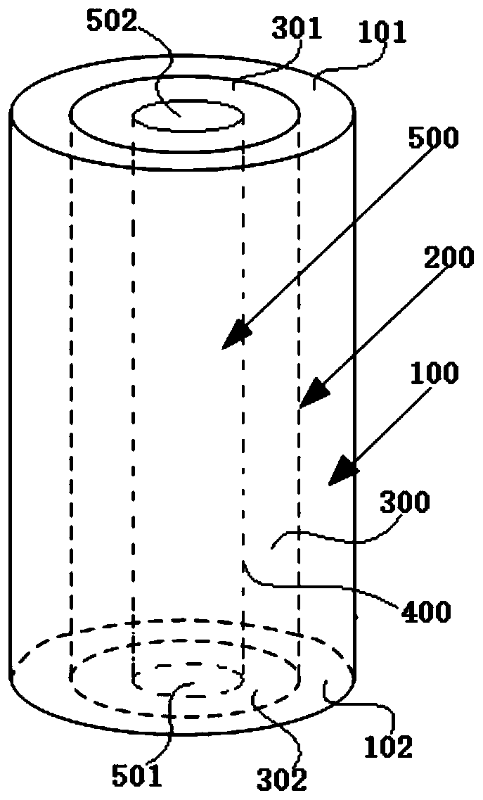
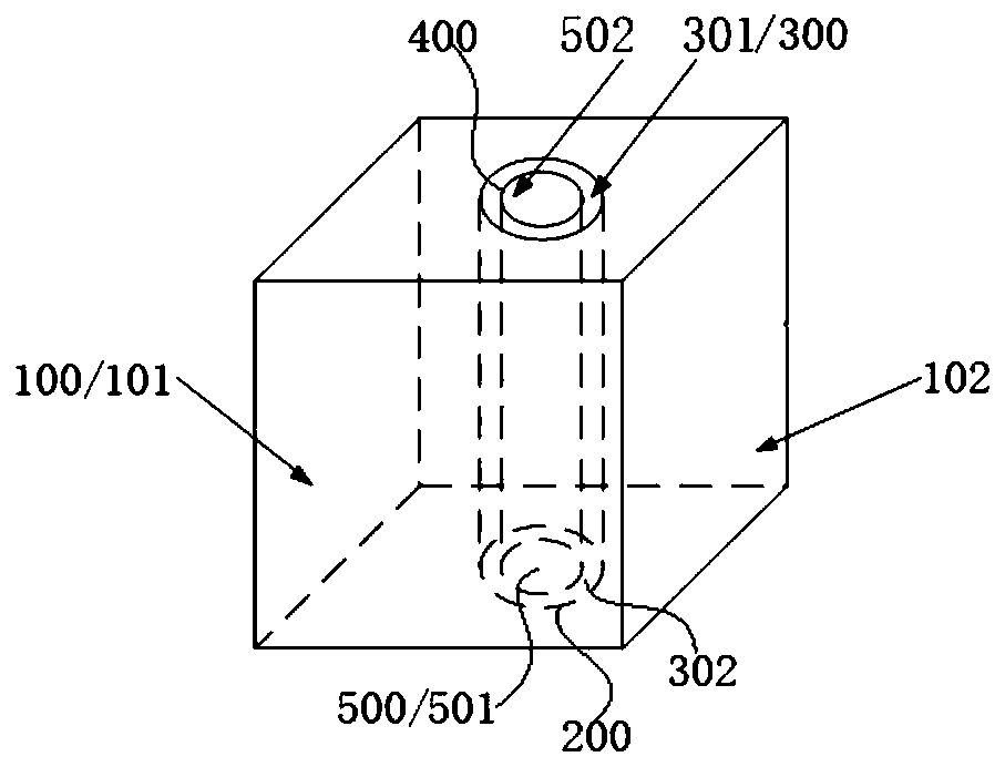
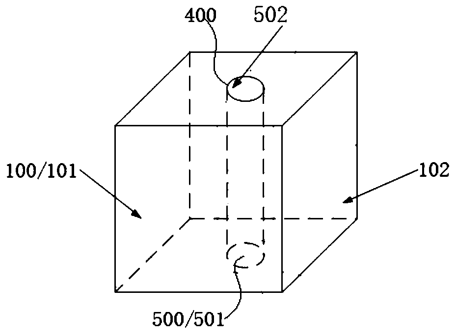
[0047] A sleeve-type heat exchange device, its partial structure schematic diagram is as follows figure 2 shown, including:

[0048] The first medium layer 100, the first medium layer 100 has a first medium inlet 101 and a first medium outlet 102 after heat exchange, the first medium in the first medium layer 100 is flue gas from an incinerator, and its flow rate is 80000Nm 3 / h;

[0049] 20 first heat exchange walls 200, 20 first heat exchange walls 200 are located in the inner periphery of the first medium layer 100, and the outer wall of the first heat exchange wall 200 is connected with the first medium layer 100, the first heat exchange wall The material of 200 is boiler steel 20G, the outer diameter is d o2 =57mm, inner diameter d i2 =49mm, thermal conductivity λ 2 =40W / (m K), the convective heat transfer coefficient h between the flue gas in the first medium layer and the first heat exchange wall o =200W / (m 2 K), length l=1m;

[0050] 20 liquid metal layers 300,...


PUM


Abstract

The invention discloses a heat exchange device and a garbage disposal system with the same. The heat exchange device comprises a first medium layer, a first heat exchange wall, a liquid metal layer, asecond heat exchange wall and a second medium layer, wherein the first medium layer is provided with a first medium inlet and a first medium outlet after heat exchange; the first heat exchange wall is located on an inner periphery of the first medium layer, and an outer wall of the first heat exchange wall is connected with the first medium layer; the liquid metal layer is located on the inner periphery of the first heat exchange wall, is connected with the inner wall of the first heat exchange wall and is provided with a liquid metal inlet and a heat-exchanged liquid metal outlet; the secondheat exchange wall is located on the inner periphery of the liquid metal layer, and an outer wall of the second heat exchange wall is connected with the liquid metal layer; the second medium layer islocated on the inner periphery of the second heat exchange wall, is connected with the inner wall of the second heat exchange wall and is provided with a second medium inlet and a second medium outlet after heat exchange. By using the heat exchange device, a temperature of the low-temperature medium can be increased, and simultaneously the temperature of a wall surface of the heat exchange wall in contact with a high-temperature medium is prevented from being obviously increased, and a problem of corrosion of the wall surface of the heat exchange wall in contact with the high-temperature medium due to low-temperature medium parameter increase is solved.

Description

technical field [0001] The invention belongs to the technical field of heat damage prevention, in particular, the invention relates to a heat exchange device and a garbage treatment system with the same. Background technique [0002] With the acceleration of urbanization in my country, there is a large gap in the demand for domestic waste disposal. By 2020, the urbanization rate of the permanent population in the mainland will reach 60%, the urbanization rate of the registered population will reach about 45%, the scale of waste incineration will reach approximately 620,000 tons / day, and at least 300,000 tons / day of waste incineration power generation will need to be added. day or more, which is equivalent to building 300 new 1,000-ton / day waste incineration power plants. [0003] At present, domestic waste incineration power generation systems generally use medium-temperature and medium-pressure steam parameters (400°C, 4MPa). With technological progress and changes in indu...

Claims


Application Information

Patent Timeline
Patent Type & Authority Applications(China)
IPC IPC(8): F28D15/00F23G5/46F22B1/18
CPCF22B1/18F23G5/46F23G2206/203F28D15/00Y02E20/12
Inventor 于超徐建炎鲍化坤郝玉刚
Owner CHINA ENFI ENGINEERING CORPORATION
Why Eureka
Try Eureka