
Resonant current sensor for PCB current measurement

A current sensor and current measurement technology, which is applied in the field of sensors, can solve the problems of high measurement accuracy of fluxgate current sensors, low accuracy of Hall current sensors, and influence on sensor accuracy, so as to save signal processing circuits, suppress temperature drift, Strong anti-interference ability

Active Publication Date: 2020-03-24
NANJING UNIV OF SCI & TECH
View PDF9 Cites 2 Cited by
  • Summary
  • Abstract
  • Description
  • Claims
  • Application Information

AI Technical Summary

Problems solved by technology

These types of current sensors also have some application limitations, such as the low accuracy of the Hall current sensor, the high measurement accuracy of the fluxgate current sensor but the high price, and the thermal drift of the giant magnetoresistive current sensor has a great impact on the accuracy of the sensor.
The output of these current sensors is a weak analog signal, and complex circuits and methods such as low-noise signal amplifiers, filters, A / D converters, and digital signal processors are required to process the sensing signals, which limits its scope of use.

Method used


Image

  • Resonant current sensor for PCB current measurement
  • Resonant current sensor for PCB current measurement
  • Resonant current sensor for PCB current measurement

Examples


Embodiment 1

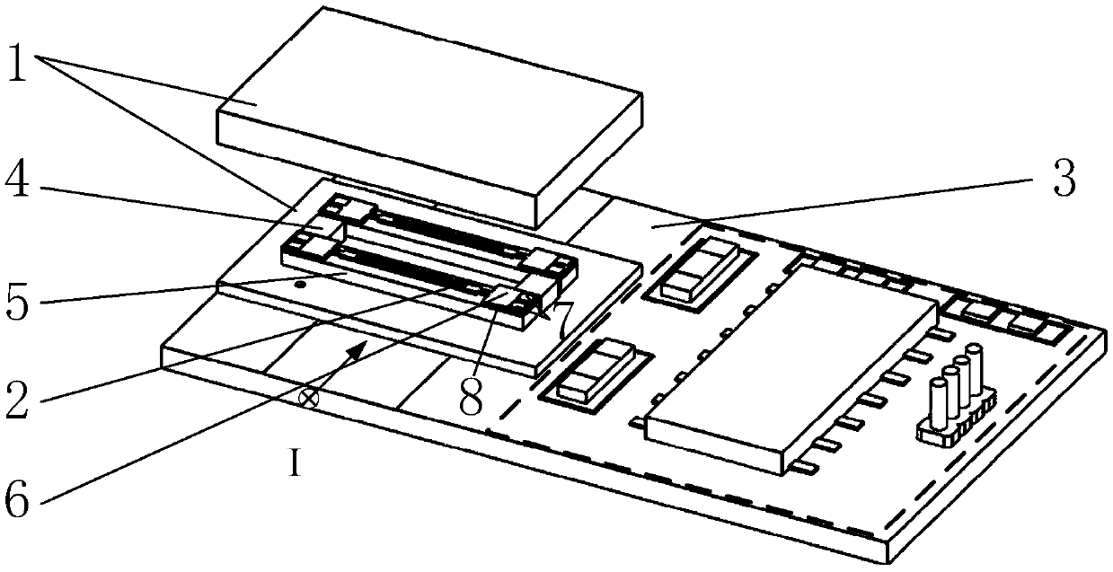
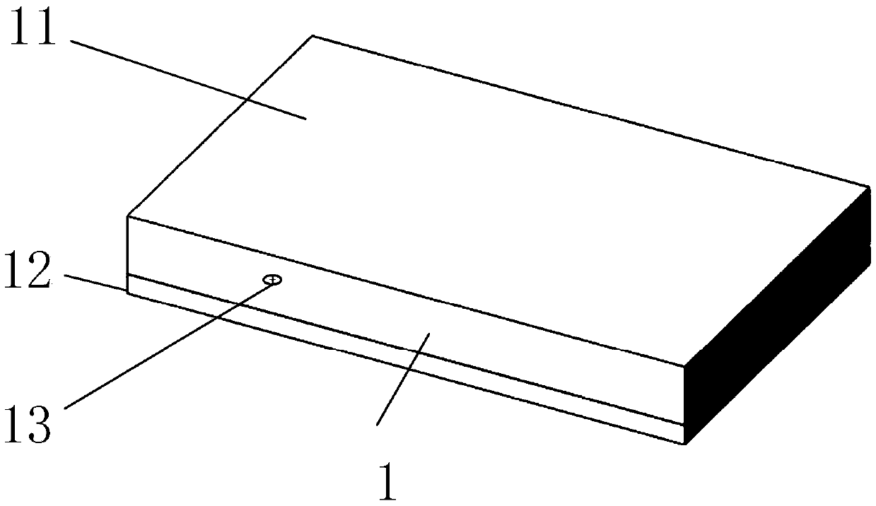
[0045] Such as figure 1 As shown, a resonant current sensor for PCB current measurement includes a resonant current sensing unit 6, a permanent magnet 4, a ceramic vacuum package shell 1, and a PCB board 3, wherein the resonant current sensing unit includes a magnetostrictive Unit 5, 2 quartz spacers 8, 1 quartz resonator 2. A current-carrying copper trace, an oscillating circuit, and an XOR frequency mixing circuit are laid on the PCB, and the current-sensitive unit 6 and the permanent magnet 4 are directly attached to the surface of the PCB current-carrying copper trace through the substrate.

[0046] The quartz resonator 2 is a double-beam quartz tuning fork fixed at both ends, and there are driving electrodes 7 at both ends of the tuning fork for connecting to an external oscillating circuit. The quartz resonator 2 works in a bending vibration mode, and the vibration directions of the two beams are symmetrical and opposite.

[0047] Quartz spacer 8 is as the transmission...

Embodiment 2

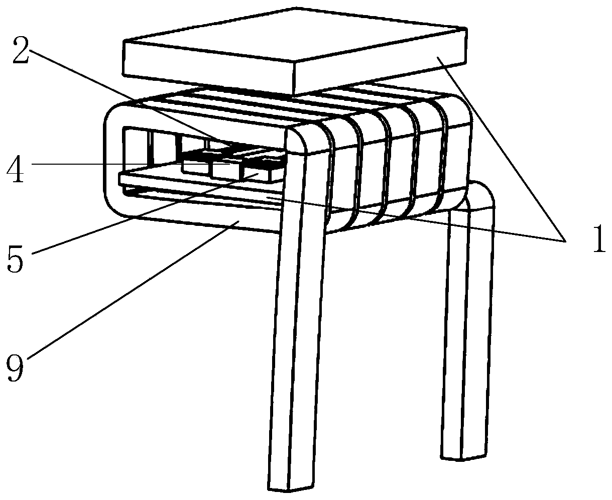
[0061] Such as image 3 As shown, the difference between this embodiment and Embodiment 1 is that the current to be measured flows through the rectangular coil 9 in this embodiment, that is, the resonant current sensitive unit and the permanent magnet are packaged in the ceramic shell 1, and the rectangular coil 9 is wound on around the housing 1 while the coil pins are connected to the onboard copper traces.

[0062] Preferably, the double-ended fixed tuning fork resonator 2 in this embodiment is the same as that in Embodiment 1.

[0063] In addition to the advantages described in Example 1, Example 2 also has the advantage of increased sensitivity compared to Example 1.


PUM


Abstract

The invention discloses a resonant current sensor used for PCB current measurement. The sensor comprises two resonant current sensitive units, two permanent magnets, a ceramic vacuum packaging shell and a PCB. The resonant current sensitive unit and the two permanent magnets are packaged in the ceramic vacuum shell. The permanent magnets are arranged between the two resonant current sensitive units. Each resonant current sensitive unit comprises a high-Q-value resonator and a magnetostriction unit. The magnetostriction unit is arranged on the lower side of the high-Q-value resonator, and the permanent magnets are arranged in a way that magnetic lines of force are emitted by the N poles of the permanent magnets and return to the S pole of the other permanent magnet through the magnetostriction unit to form a closed magnetic loop. According to the invention, an XOR frequency mixing differential output mode is adopted, and the sensor has the characteristics of high sensitivity, effectiveinhibition of temperature drift and strong anti-interference capability.

Description

technical field [0001] The invention belongs to sensor technology, in particular to a resonant current sensor used for PCB current measurement. Background technique [0002] In power electronic systems, current sensing technology is the most widely used sensing and measurement technology. Printed circuit board (PCB), as one of the most basic and active industries in the electronics industry, has developed rapidly, and with the increasing development of semiconductor design and manufacturing technology, printed circuit boards are also moving towards ultra-thin, high-density, multi-layer Number, high performance and other directions of development. However, while achieving rapid development, the PCB industry is also facing a huge challenge, which is the quality of PCB. Due to many uncertain factors between the current trace, the integrated circuit and various components on the circuit board, PCB faults will occur. If the faults are not eliminated in time, hidden dangers will...

Claims


Application Information

Patent Timeline
IPC IPC(8): G01R19/00
CPCG01R19/0092
Inventor 李辉卞雷祥彭伟民黄子军文玉梅李平
Owner NANJING UNIV OF SCI & TECH
Features
  • Generate Ideas
  • Intellectual Property
  • Life Sciences
  • Materials
  • Tech Scout
  • Unparalleled Data Quality
  • Higher Quality Content
  • 60% Fewer Hallucinations
Learn More