
A power coordination controller applied to optical storage system

A technology for coordinating controllers and photovoltaic storage systems, applied in the direction of control/regulation systems, instruments, collectors, etc., can solve the problem of less application of photovoltaic controllers, and achieve high-efficiency operation, fast response, and high control reliability Effect

Active Publication Date: 2022-03-25
LANZHOU JIAOTONG UNIV
View PDF5 Cites 0 Cited by
  • Summary
  • Abstract
  • Description
  • Claims
  • Application Information

AI Technical Summary

Problems solved by technology

[0003] In recent years, the application of coordinated control in various fields has become more and more extensive, but the application in photovoltaic controllers is less

Method used


Image

  • A power coordination controller applied to optical storage system
  • A power coordination controller applied to optical storage system
  • A power coordination controller applied to optical storage system

Examples


Embodiment 1

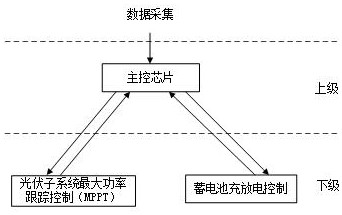
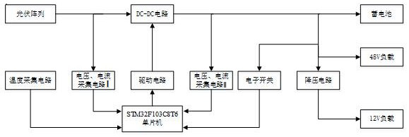
[0034] Example 1, reference figure 1 A power coordination controller applied to the light storage system, including photovoltaic power generation systems (solar cells), single-chip microcomputer and battery pack (energy storage devices), single-chip control photovoltaic power generation system and battery pack, photovoltaic power generation system and battery pack All are connected. Its specific configuration: including voltage acquisition circuit I and voltage acquisition circuit II, current collecting circuit I and current collecting circuit II, DC-DC circuit, drive circuit, temperature acquisition circuit; wherein the voltage acquisition circuit I and voltage collecting circuit II are connected to Single chip pin PA1, PA2; Current Acquisition Circuit I and Current Acquisition Circuit II are connected to the single-chip pin PA4 and PA5; DC-DC circuit connects the microcontroller, drive circuit connects to the single-chip pin PA8; temperature capture The circuit is connected to t...

Embodiment 2

[0045] Example 2, reference figure 1 One power coordination controller applied to the light storage system, further comprising an electronic switch, one end connecting to a single-chip PB10, and the other end connecting to the load and battery pack. Using electronic switches to achieve overprofit protection. The electronic switch uses the MOS tube control load to prevent the controller from generating overcurrent, short circuit, and overload. The battery system is frequently rushed through the discharge, which will affect the life of the battery, and the long-term life of the battery pack has a greater impact on the life of the photovoltaic power generation system, and the key to extend the service life of the battery pack is to control the charge and discharge process. .

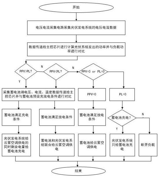
[0046] Refer figure 2 A power coordination controller applied to the light storage system, wherein the single-chip microcomputer controls the photovoltaic power generation system and the battery pack, which wil...


PUM


Abstract

A power coordinating controller applied to the photovoltaic storage system, the single-chip microcomputer controls the photovoltaic power generation system and the battery pack, the photovoltaic power generation system and the battery pack are connected to the load, and has voltage acquisition circuits I and II, current acquisition circuits I and II, and DC‑DC Circuit, drive circuit, temperature acquisition circuit; voltage acquisition circuit Ⅰ and voltage acquisition circuit Ⅱ are connected to pins PA1 and PA2 of the microcontroller; current acquisition circuit Ⅰ and current acquisition circuit Ⅱ are connected to pins PA4 and PA5 of the microcontroller; DC‑DC The circuit is connected to the single-chip microcomputer through the driving circuit, and the driving circuit is connected to the pin PA8 of the single-chip microcomputer; the temperature acquisition circuit is connected to the pin PA6 of the single-chip microcomputer; the photovoltaic power generation system is connected to the battery pack through the DC-DC circuit; the first load forms the second load through the step-down circuit. Load available voltage. The invention realizes the cooperation between the photovoltaic power supply and the charging and discharging mode of the storage battery under the maximum power state, and realizes long-term and stable operation of the joint power supply of the photovoltaic power generation system and the storage battery group with a large load.

Description

Technical field [0001] The present invention belongs to the field of photovoltaic power control, specifically refers to a power coordinated controller applied to a light storage system and a power coordinated control method. Background technique [0002] The solar energy is not exhausted, inexhaustible, the initial energy cost is low, and you can supply it everywhere, you don't have to transport long distance. Therefore, using the independent photovoltaic power generation system to supply power to the load, the use of electricity equipment used to use the power supply has certain competitiveness in the market, and the policy of implementing the country's open domestic photovoltaic market, promoting photovoltaic and architectural integration in China Very important. [0003] In recent years, coordinated control has become more extensive in various fields, but there are fewer applications in photovoltaic controllers. Inventive content [0004] The present invention provides a powe...

Claims


Application Information

Patent Timeline
Patent Type & Authority Patents(China)
IPC IPC(8): H02J7/35H02J3/32G05F1/67
CPCH02J7/35H02J3/32G05F1/67Y02E70/30Y02E10/56
Inventor 董海鹰张凯王怀江代爽王芸芸李国胜
Owner LANZHOU JIAOTONG UNIV
Learn More