Portable bacterial lysis device based on centrifugal microfluidic technology and using method thereof

A cracking device and portable technology, which is applied in the field of portable bacterial cracking devices, can solve the problems of complex microfluidic chip and device structure, low sample processing throughput, and reduced method practicability, so as to improve sample processing throughput and use mode Flexible, easy-to-operate effects

Inactive Publication Date: 2020-03-31
DALIAN MARITIME UNIVERSITY
View PDF7 Cites 3 Cited by
  • Summary
  • Abstract
  • Description
  • Claims
  • Application Information

AI Technical Summary

Problems solved by technology

The existing microfluidic chip-based bacterial lysis methods often have low sample processing throughput, co

Method used


Image

  • Portable bacterial lysis device based on centrifugal microfluidic technology and using method thereof
  • Portable bacterial lysis device based on centrifugal microfluidic technology and using method thereof
  • Portable bacterial lysis device based on centrifugal microfluidic technology and using method thereof

Examples


Embodiment 1

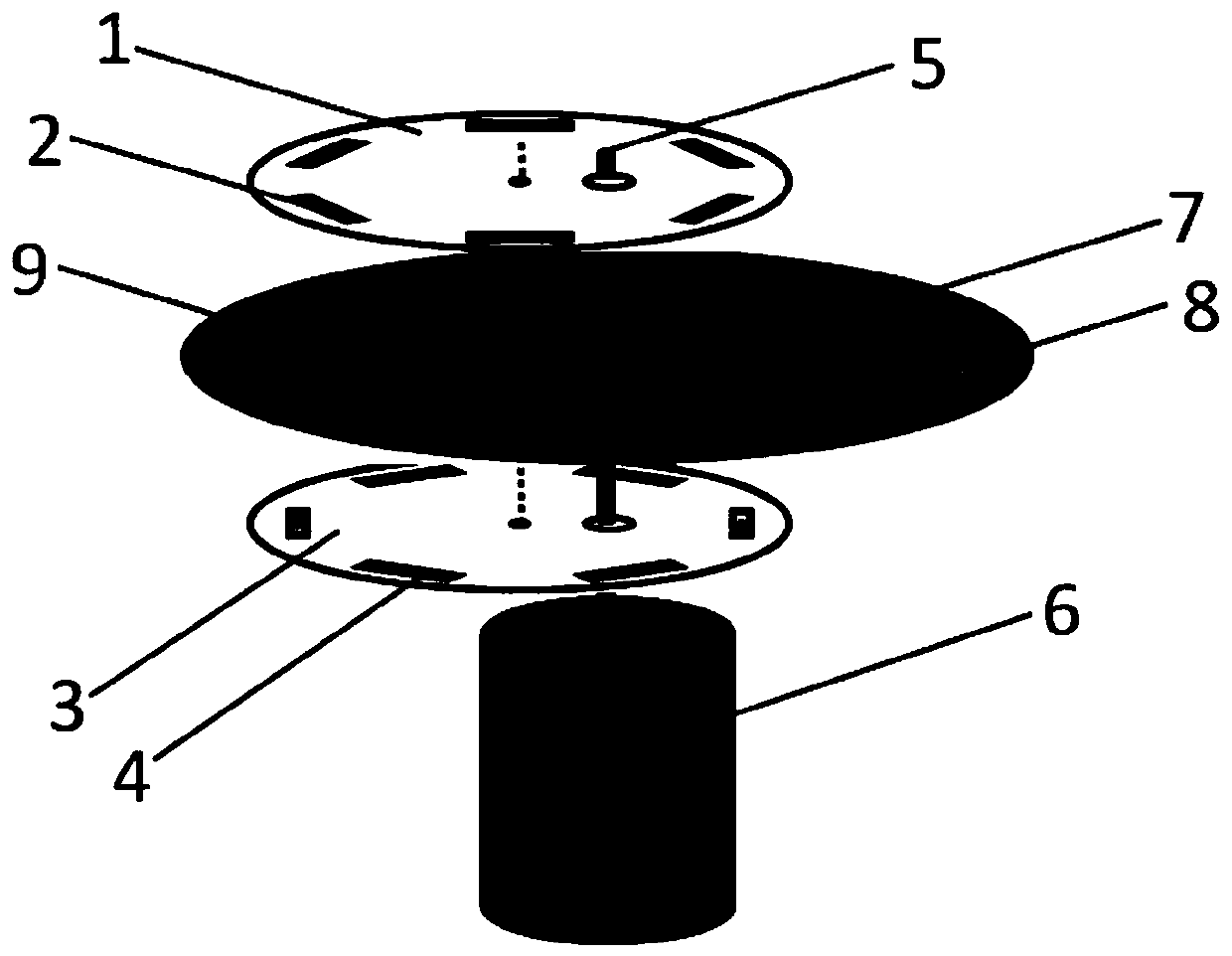
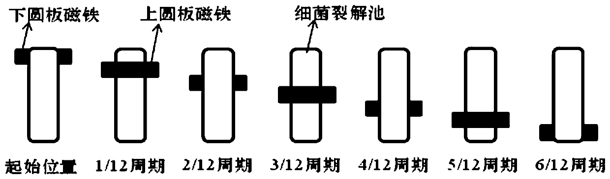
[0027] figure 1 is a schematic diagram of the structure of a portable bacterial lysing device based on centrifugal microfluidic technology, by figure 1 As shown, the device of the present invention consists of an upper disc 1, an upper disc magnet 2, a lower disc 3, a lower disc magnet 4, a rotating shaft 5, a drive motor 6, a chip tray 7, a disc microfluidic chip 8 and The bacteria lysing pool consists of 9 components. Specifically, the upper circular plate 1 and the lower circular plate 3 are arranged parallel to each other, the disk microfluidic chip 8 is located between the upper and lower circular plates and arranged parallel to the circular plates, and the rotating shaft 5 vertically runs through the two circular plates and Disc microfluidic chip 8, the rotating shaft 5 passes through the position deviated from the center of the circle on the disc and does not contact the disc, the rotating shaft 5 passes through the position of the center of the circle on the disc micr...

Embodiment 2

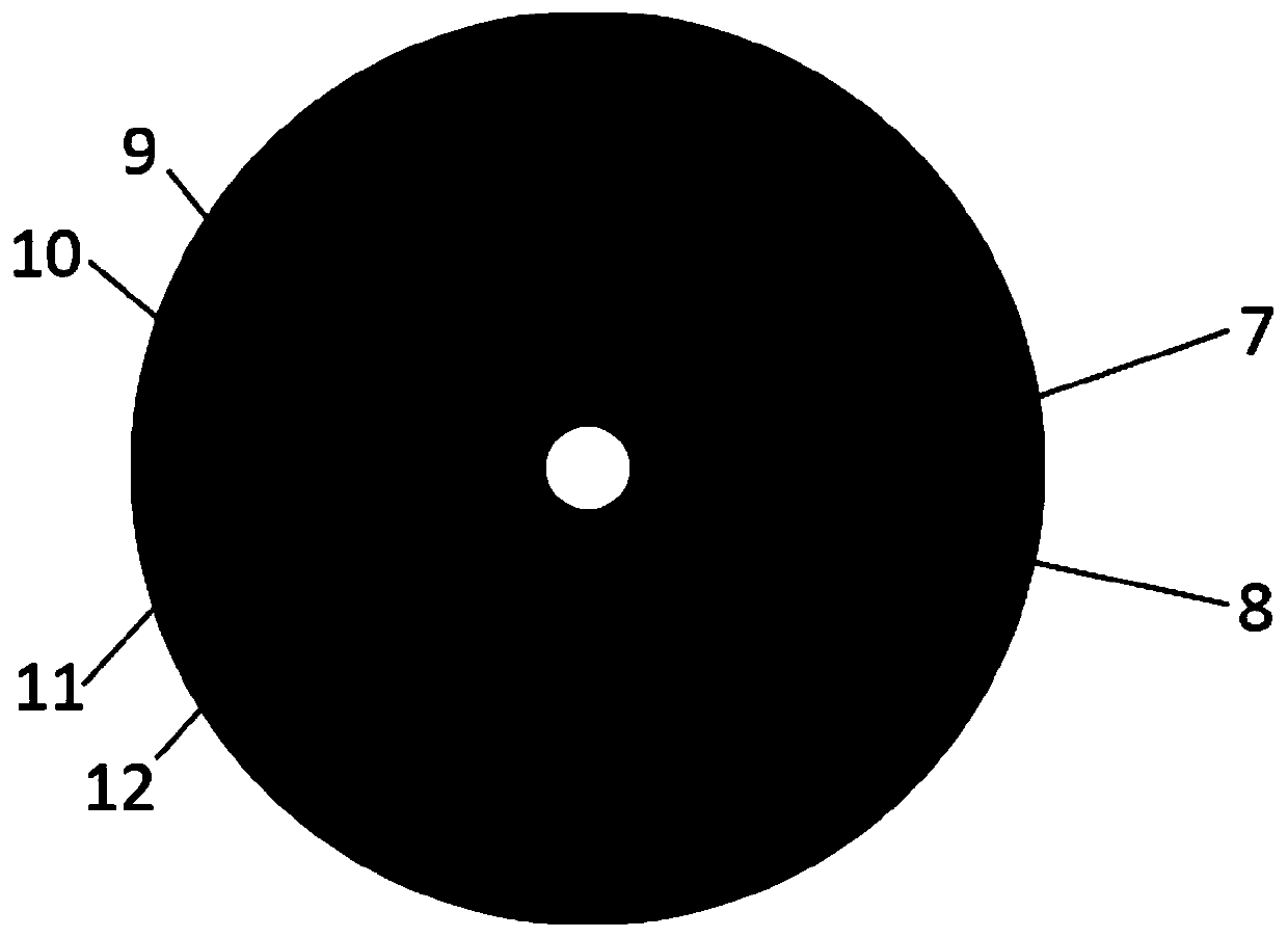
[0036] Figure 5 It is a top view of the disk microfluidic chip and the chip tray structure. The microfluidic chip includes 18 bacterial lysis pools, which can be used for efficient and rapid lysis of many bacterial samples. Among them, the outer diameter of the chip tray is 70mm, the diameter of the disc microfluidic chip is 60mm, and the size of the bacterial lysis cell is 11.8×3.5mm 2 , The diameter of the circular magnet is 2mm.

Embodiment 3

[0038] Figure 6 It is a top view of the sliced ​​disc microfluidic chip and tray structure. A complete disc microfluidic chip is divided into 6 pieces on average, and each area includes 2 bacterial lysis pools; each piece can be used alone or in multiples. Used in combination, it can be used for high-efficiency lysis of a small number of multiple times or different numbers of bacterial samples.


PUM

PropertyMeasurementUnit
Diameteraaaaaaaaaa
Thicknessaaaaaaaaaa
Outer diameteraaaaaaaaaa

Abstract

The invention, which belongs to the technical field of bacterial lysis devices, discloses a portable bacterial lysis device based on a centrifugal microfluidic technology and a using method thereof. The device comprises upper and lower circular plates, a disc micro-fluidic chip, and a rotating shaft, wherein the disc micro-fluidic chip and the rotating shaft are parallel to each other between theupper and lower circular plates. The rotating shaft passes through the parts, away from the circle centers, of the circulate plates but is not in contact with the circular plates; and the rotating shaft passes through the circle center of the disc micro-fluidic chip. A plurality of magnets are respectively arranged on the circular plates and are uniformly distributed on each circular plate, wherein the magnets are mutually staggered in a vertical position. A plurality of bacteria lysis pools are arranged on the disc micro-fluidic chip. According to the invention, the bacterial lysis efficiencyand the sample treatment flux can be effectively improved; and other operation units can be integrated to realize real-time on-site detection of bacteria. The designed bacterial lysis device is portable, low in cost, easy and convenient to operate; the operation is automatic; and the device is used flexibly. The portable bacterial lysis device can meet different requirements and has the broad application prospects.

Description

technical field [0001] The invention belongs to the technical field of bacterial lysing devices, and in particular relates to a portable bacterial lysing device based on centrifugal microfluidic technology and an application method thereof. Background technique [0002] Bacteria detection and analysis are widely used in bacterial research and the prevention and monitoring of pathogenic bacteria. The first step is bacterial lysis. Traditional bacterial lysis methods, such as boiling method, ultrasonic lysis method, enzymatic lysis method, chemical lysis method, etc., often involve special devices or reagents in the lysis process, resulting in low lysis efficiency and high cost, and it is difficult to integrate other operating units, for real-time field applications. Microfluidic chip, also known as lab-on-a-chip, is the science and technology of processing or manipulating fluid in micron-scale space. It forms a network with micro-channels and runs through the entire system w...

Claims


Application Information

Patent Timeline
IPC IPC(8): C12M1/00C12M1/42C12Q1/24
CPCC12M23/16C12M23/34C12M35/06C12Q1/24
Inventor 钟润涛赵媛潘汉卿王少华王梦雨孙野青
Owner DALIAN MARITIME UNIVERSITY
Why Eureka
Try Eureka