Distributed energy storage device based on controllable DC bus

A distributed energy storage and DC bus technology, which is applied in the direction of output power conversion device, conversion of DC power input to DC power output, conversion of AC power input to DC power output, etc., can solve the problem of high total DC voltage constraints and heat dissipation requirements Strong, two-way voltage regulation difficulties and other problems, to achieve the effect of reducing the total DC voltage constraint, reducing energy storage costs, and better results

Active Publication Date: 2022-02-15
SOUTHEAST UNIV
View PDF5 Cites 0 Cited by
  • Summary
  • Abstract
  • Description
  • Claims
  • Application Information

AI Technical Summary

Problems solved by technology

[0005] The technical problem to be solved by the present invention is the high internal resistance loss and the difficulty of bidirectional voltage regulation in the energy storage device based on the chain-link converter under the low-voltage and high-power distributed energy storage operating environment, and the problems brought about by the above problems There are many problems such as strong heat dissipation requirements, low device efficiency, high total DC voltage constraints, and high energy storage costs.

Method used


Image

  • Distributed energy storage device based on controllable DC bus
  • Distributed energy storage device based on controllable DC bus
  • Distributed energy storage device based on controllable DC bus

Examples


Embodiment 1

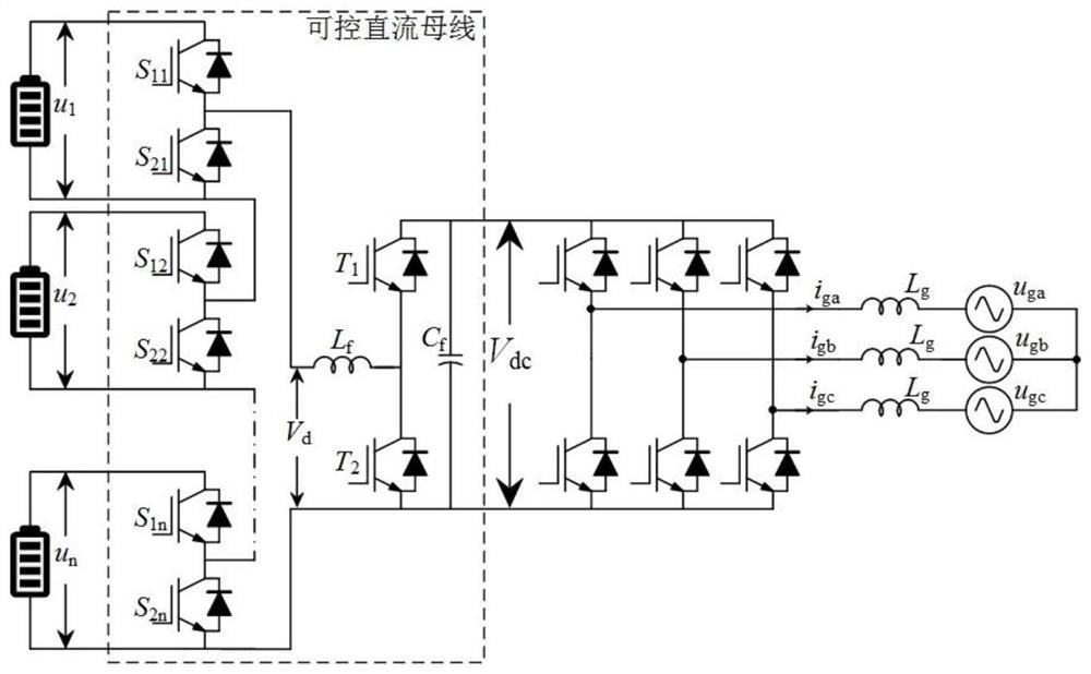
[0024] Topology of distributed energy storage device based on controllable DC bus. Combine below figure 1 The system provided in this embodiment will be described in detail.

[0025] see figure 1 , the topology of a distributed energy storage device based on a controllable DC bus, the structure includes: multiple energy storage modules, multiple half-bridge circuits, buck / boost bidirectional voltage regulation circuits, three-phase bridge converters, and power grids side filter inductor.

[0026] The energy storage module and the half-bridge modules are electrically connected one by one, and the half-bridge modules are sequentially cascaded to form a chain circuit, and the chain circuit is electrically connected to the buck / boost bidirectional voltage regulation circuit, and the buck / boost The bidirectional voltage regulating circuit is electrically connected with the three-phase bridge converter, the filter inductor on the grid side, and the AC grid in sequence.

[0027] ...

Embodiment 2

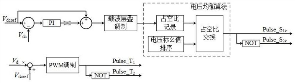
[0031] Control algorithm of distributed energy storage device based on controllable DC bus. Combine below Figure 2 to Figure 4 The system provided in this embodiment will be described in detail.

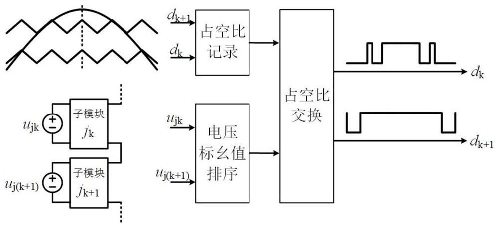
[0032] see Figure 2 to Figure 4 , the control algorithm of the distributed energy storage device based on the controllable DC bus, the algorithm includes: a chain structure control algorithm, a buck / boost bidirectional voltage regulation circuit control algorithm, and a three-phase bridge converter control algorithm.

[0033] The chain structure control algorithm adopts the voltage loop, and the trigger signal of the switching tube is obtained through the PI controller, the carrier cascade modulation, and the voltage equalization algorithm: sampling the output voltage V of the buck / boost bidirectional voltage regulation circuit dc , given by the DC bus voltage V dcref Make a difference with the sampled value, input the difference value into the PI controller and add the limiter,...


PUM


Abstract

The invention discloses a distributed energy storage device based on a controllable DC bus. The energy storage device includes a controllable DC bus part and an inverter part. The controllable DC bus part is a chain circuit composed of a plurality of half-bridge circuits. It is composed of a buck / boost bidirectional voltage regulation circuit, and the inverter part is composed of a three-phase bridge converter. The chain-type circuit obtains the switching signal from the voltage loop through the cascading modulation of the carrier added to the voltage equalization algorithm. The buck / boost bidirectional voltage regulation circuit obtains the switching signal by dividing the voltage sampling value by the voltage given value through PWM modulation. The inverter circuit is composed of vector-based The grid-connected algorithm of the control is modulated by PWM to obtain the switch signal. The proposed DC bus structure combines the step-down advantages of the chain circuit and the boost advantages of the buck / boost circuit. It has the advantages of simple control method, stable DC bus voltage, reduced energy storage cost and internal resistance loss, and balanced output of each energy storage unit. , strong versatility and easy expansion, etc., adapt to the special operating environment of low-voltage and high-power distributed energy storage.

Description

technical field [0001] The invention relates to a distributed energy storage device, in particular to a distributed energy storage device based on a controllable DC bus, which belongs to the field of distributed energy storage applications. Background technique [0002] With the development of ultra-high voltage power transmission and energy Internet technology, the real-time supply of a large number of incoming electricity from outside the region and the continuous operation of new energy generating units have alleviated the huge power demand brought about by the rapid economic development of my country's eastern coastal areas and reduced the environmental protection of the atmosphere. Governance pressure. However, the transmission capacity of UHV lines is huge. Once abnormal fluctuations or emergencies occur, local power shortages will occur, and even large-scale system oscillations or disconnections will occur, resulting in serious economic losses and adverse social impact...

Claims


Application Information

Patent Timeline
Patent Type & Authority Patents(China)
IPC IPC(8): H02M3/158H02M7/5387H02J3/28H02J3/38
CPCH02M3/1582H02M7/53875H02M7/5395H02J3/28
Inventor 陈武叶海涵
Owner SOUTHEAST UNIV
Why Eureka
Try Eureka