Near-infrared laser surface treatment method of carbon fiber/resin matrix composites

A technology of laser surface treatment and composite materials, which is applied in the field of near-infrared laser surface treatment of carbon fiber/resin-based composite materials, and can solve the problem that processing efficiency has not been further improved

Active Publication Date: 2021-09-10
无锡锐科光纤激光技术有限责任公司
View PDF0 Cites 0 Cited by
  • Summary
  • Abstract
  • Description
  • Claims
  • Application Information

AI Technical Summary

Problems solved by technology

Some scholars have used near-infrared lasers to remove the surface resin layer of carbon fiber / epoxy resin matrix composites, but the overall effect of the treatment is similar to that of pulsed CO2. 2 The laser pretreatment effect and processing efficiency have not been further improved

Method used


Image

  • Near-infrared laser surface treatment method of carbon fiber/resin matrix composites
  • Near-infrared laser surface treatment method of carbon fiber/resin matrix composites
  • Near-infrared laser surface treatment method of carbon fiber/resin matrix composites

Examples


Embodiment 1

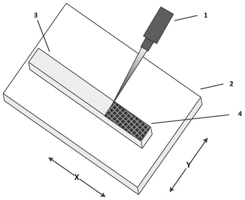
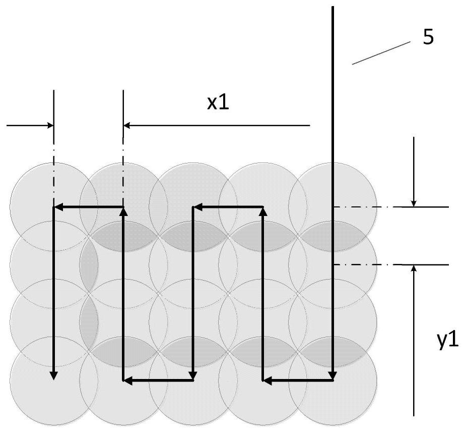
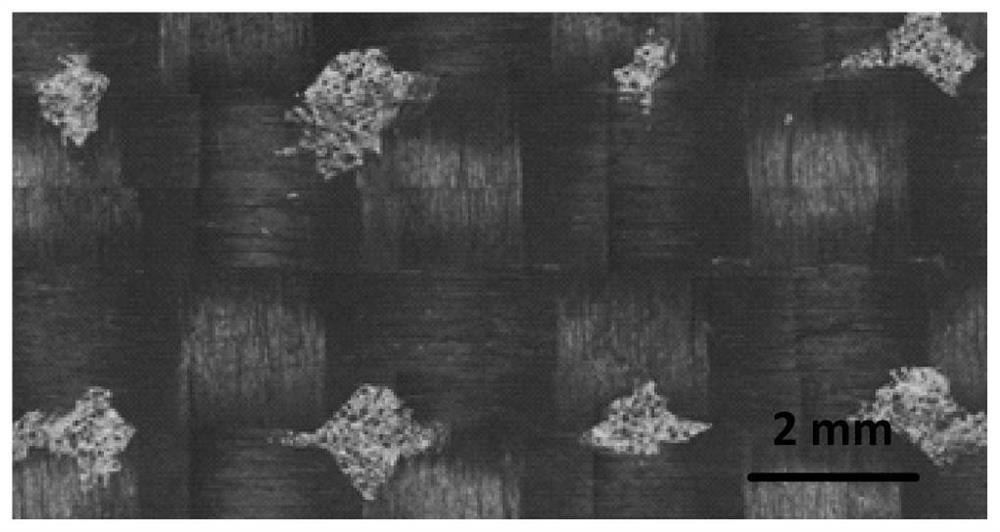
[0040] like figure 1 As shown, the laser source 1 in this embodiment is a YAG laser with a wavelength of 1064 nm, a pulse width of 7 ns, and a single pulse energy ranging from 3 to 200 mJ. A carbon fiber / epoxy resin-based composite plate with a specification of 80mm×10mm×1mm is fixed on the electronically controlled two-dimensional mobile platform 2 . The pulse energy used in this embodiment is 40 mJ, and the pulse frequency is 10 Hz. The laser source remains fixed, the laser beam is always perpendicular to the surface of the plate with a thickness of 1 mm, and the diameter of the spot on the material surface 4 is 3.8 mm. In the laser spot, the energy has a flat-top distribution, so the pulse power density received on the material surface 4 is always 5×10 7 W / cm 2 . The material surface with a specification of 80mm×10mm moves along with the moving platform 2 in a manner of step length x1=2.8mm, y1=3.8mm. Partial micrographs of the treated material surface 4 as image 3 s...

Embodiment 2

[0050] The laser source is the same as in Embodiment 1, which is a pulsed YAG laser with a wavelength of 1064 nm, a pulse width of 7 ns, and a frequency of 10 Hz. The material specification is the same as that of Embodiment 1, which is a carbon fiber / epoxy resin-based composite plate of 80mm×10mm×1mm, which is fixed on the mobile platform 2 in the same manner as in Embodiment 1. The diameter of the light spot on the material surface 4 is the same as that in Embodiment 1, which is 3.8 mm. The pulse energy used in the present invention becomes 34mJ. In the laser spot, the energy has a flat-top distribution, so the pulse power density received on the material surface 4 is always 4.3×10 7 W / cm 2 . The material surface with a specification of 80mm×10mm moves along with the moving platform 2 in a manner of step length x1=3mm, y1=2.5mm. Partial micrographs of the treated material surface 4 as Image 6 shown. Analyzed by image processing software, Image 6 The residual ratio η ...

Embodiment 3

[0053] The laser source is the same as in Embodiment 1, which is a pulsed YAG laser with a wavelength of 1064 nm, a pulse width of 7 ns, and a frequency of 10 Hz. The material specification is the same as that of Embodiment 1, which is a carbon fiber / epoxy resin-based composite plate of 80mm×10mm×1mm, which is fixed on the mobile platform 2 in the same manner as in Embodiment 1. The diameter of the light spot on the material surface 4 is the same as that in Embodiment 1, which is 3.8 mm. The pulse energy used in the present invention is 40mJ. In the laser spot, the energy has a flat-top distribution, so the pulse power density received on the material surface 4 is always 5×10 7 W / cm 2 . The material surface with a specification of 80mm×10mm moves along with the moving platform 2 in a manner of step length x1=3mm, y1=2.5mm. Partial micrographs of the treated material surface 4 as Figure 7 shown. Analyzed by image processing software, Figure 7 The residual rate η of the...


PUM

PropertyMeasurementUnit
diameteraaaaaaaaaa
diameteraaaaaaaaaa

Abstract

The invention provides a near-infrared laser surface treatment method for carbon fiber / resin-based composite materials. The inner fiber layer of the material and its surrounding resin are heated by near-infrared ns pulse laser, thereby generating high-temperature and high-pressure air mass, and the mechanical energy of the air mass expansion is used to disperse the surface layer of the material. The resin matrix is ​​completely removed. With a specific laser spot size, laser pulse power density and laser scanning method, the resin matrix can be efficiently removed from the treated surface. The invention can be used for surface cleaning, surface modification and pretreatment before bonding of carbon fiber / epoxy resin matrix composite materials.

Description

technical field [0001] The invention belongs to a material surface pretreatment method, in particular to a near-infrared laser surface treatment method of a carbon fiber / resin matrix composite material. Background technique [0002] Due to the advantages of high strength, high modulus, chemical corrosion resistance and light weight, carbon fiber / epoxy resin-based composite materials are widely used in the fields of automobiles, sports equipment and aerospace. For the connection of different structural parts of this material, traditional methods such as welding, rivets, and bolts will cause thermal damage and mechanical damage to carbon fiber / epoxy resin matrix composites, thereby causing degradation of the mechanical properties of the structural parts. The connection method of using resin glue and other adhesives to bond the surfaces of two carbon fiber / epoxy resin-based composite structural parts together overcomes the disadvantages of mechanical connection, and is currentl...

Claims


Application Information

Patent Timeline
Patent Type & Authority Patents(China)
IPC IPC(8): B29C65/48B23K26/402
CPCB23K26/402B29C65/48B29C66/028
Inventor 李啸韩冰马丁.伊尔哈特倪晓武
Owner 无锡锐科光纤激光技术有限责任公司
Why Eureka
Try Eureka