Biomass gas and natural gas coupling power generation device
A technology for biomass gas and power generation devices, which is applied to gas turbine devices, biofuels, and the manufacture of combustible gases, etc., can solve the problems of high cost, complex gasification agent process, and high cost of natural gas power generation. Inexpensive effect
- Summary
- Abstract
- Description
- Claims
- Application Information
AI Technical Summary
Problems solved by technology
Method used
Image

Examples
Embodiment 1
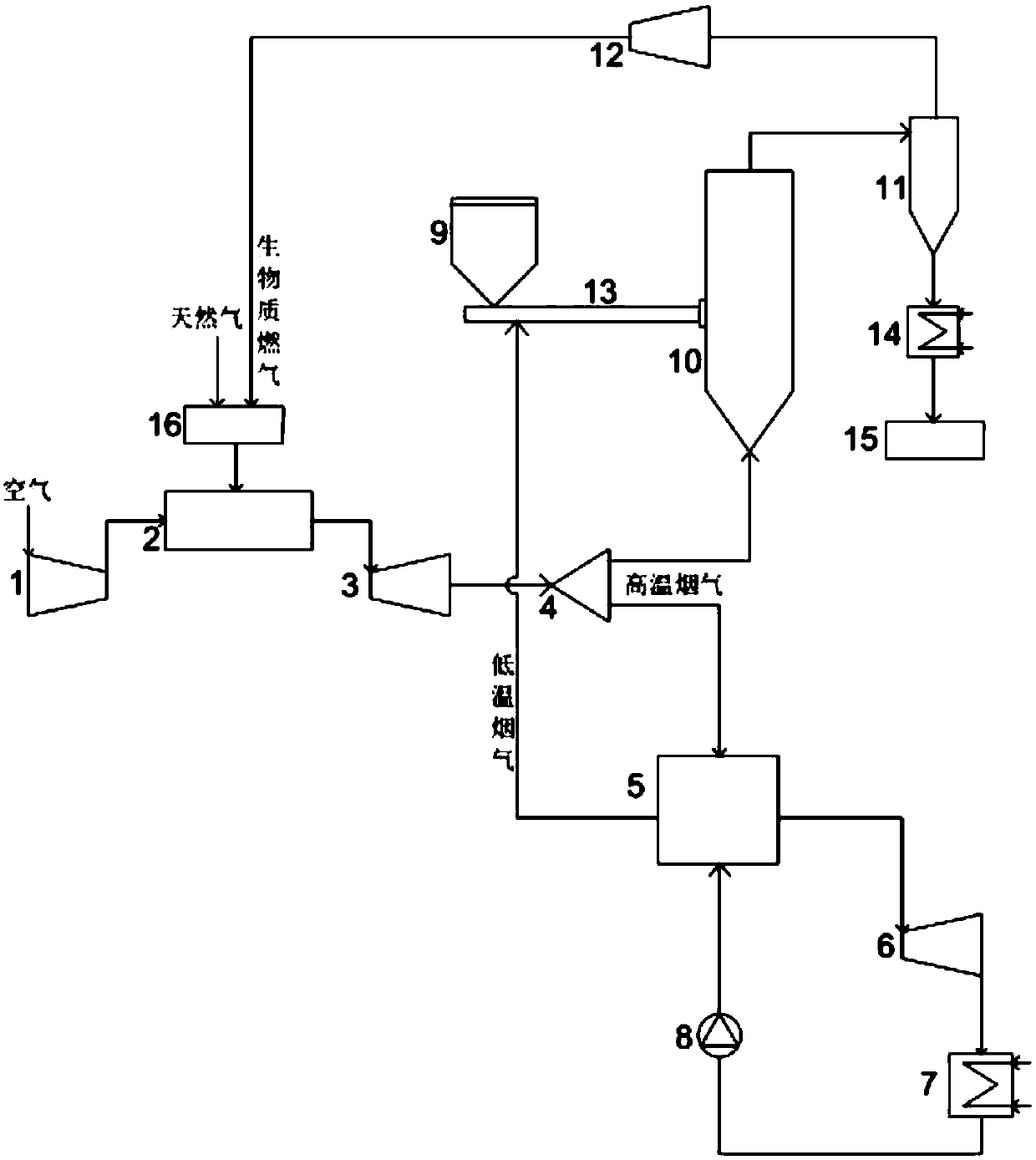
[0023] A biomass gas and natural gas coupling power generation device, including a combined cycle power generation device and a biomass gasification device; the combined cycle power generation device includes a compressor 1, a gas turbine combustion chamber 2, a gas turbine turbine 3, a separator 4, waste heat A boiler 5, a steam turbine 6, a condenser 7 and a water pump 8; the biomass gasification device includes a biomass feeding hopper 9, a biomass gasifier 10, a cyclone separator 11 and a gas compressor 12;
[0024] The outlet end of the gas turbine 1 is connected to the gas turbine combustor 2, and the compressor 1 is used to compress the air and then transport it to the gas turbine combustor 2 as a combustion oxidant; the outlet port of the gas turbine combustor 2 is connected to the gas turbine turbine The gas turbine 3 is connected to the gas turbine 3, and the gas turbine 3 is used to expand the flue gas produced by combustion to drive the generator to generate electri...
Embodiment 2
[0027] A biomass gas and natural gas coupling power generation device, including a combined cycle power generation device and a biomass gasification device; the combined cycle power generation device includes a compressor 1, a gas turbine combustion chamber 2, a gas turbine turbine 3, a separator 4, waste heat A boiler 5, a steam turbine 6, a condenser 7 and a water pump 8; the biomass gasification device includes a biomass feeding hopper 9, a biomass gasifier 10, a cyclone separator 11 and a gas compressor 12;
[0028] The outlet end of the gas turbine 1 is connected to the gas turbine combustor 2, and the compressor 1 is used to compress the air and then transport it to the gas turbine combustor 2 as a combustion oxidant; the outlet port of the gas turbine combustor 2 is connected to the gas turbine turbine The gas turbine 3 is connected to the gas turbine 3, and the gas turbine 3 is used to expand the flue gas produced by combustion to drive the generator to generate electri...
Embodiment 3
[0032] A biomass gas and natural gas coupling power generation device, including a combined cycle power generation device and a biomass gasification device; the combined cycle power generation device includes a compressor 1, a gas turbine combustion chamber 2, a gas turbine turbine 3, a separator 4, waste heat A boiler 5, a steam turbine 6, a condenser 7 and a water pump 8; the biomass gasification device includes a biomass feeding hopper 9, a biomass gasifier 10, a cyclone separator 11 and a gas compressor 12;
[0033] The outlet end of the gas turbine 1 is connected to the gas turbine combustor 2, and the compressor 1 is used to compress the air and then transport it to the gas turbine combustor 2 as a combustion oxidant; the outlet port of the gas turbine combustor 2 is connected to the gas turbine turbine The gas turbine 3 is connected to the gas turbine 3, and the gas turbine 3 is used to expand the flue gas produced by combustion to drive the generator to generate electri...
PUM
 Abstract
Description
Claims
Application Information
 - R&D
- Intellectual Property
- Life Sciences
- Materials
- Tech Scout
- Unparalleled Data Quality
- Higher Quality Content
- 60% Fewer Hallucinations
Browse by: Latest US Patents, China's latest patents, Technical Efficacy Thesaurus, Application Domain, Technology Topic, Popular Technical Reports.
© 2025 PatSnap. All rights reserved.Legal|Privacy policy|Modern Slavery Act Transparency Statement|Sitemap|About US| Contact US: help@patsnap.com