Hydro-cracking method of catalytic diesel oil

A technology for hydrocracking and catalyzing diesel oil, which is applied in hydrotreating process, petroleum industry, processing hydrocarbon oil, etc., can solve the problems of uncontrollable refining reactor and cracking reactor, etc., to avoid temperature mismatch, sulfur and nitrogen content, etc. Low, high octane effect

Pending Publication Date: 2020-05-01
CHINA PETROLEUM & CHEM CORP +1
View PDF9 Cites 0 Cited by
  • Summary
  • Abstract
  • Description
  • Claims
  • Application Information

AI Technical Summary

Problems solved by technology

Traditional technology cannot achieve targeted control of H in refining reactors and cracking reactors 2 S and NH 3 Concentration, so as to realize the activity control of hydrofinishing agent and hydrocracking agent

Method used


Image

  • Hydro-cracking method of catalytic diesel oil
  • Hydro-cracking method of catalytic diesel oil
  • Hydro-cracking method of catalytic diesel oil

Examples


Embodiment 1

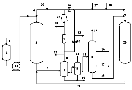
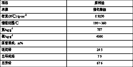
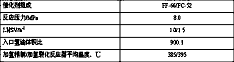
[0036] Catalyzed diesel oil is used as raw material, and the industrial hydrofinishing agent FF-66 and hydrocracking agent FC-52 system are selected. figure 1 The operating process and implementation process conditions are as shown in Table 3. In the initial stage of device operation, cyclohexylamine is injected into the raw material tank to control the concentration of acidic water at 1000-8000 ppm, and the concentration of hydrogen sulfide at the inlet of the circulating hydrogen compressor is controlled at 20-150 ppm. After the product is qualified, close the side line control valve 10 of the circulating hydrogen desulfurization tower, open the control valve 26, and control the circulating hydrogen concentration at the outlet of the circulating hydrogen desulfurization tower at 500-1000 ppm. At the end of the operation of the device, open the control valve 10 and close the control valve 26 to control the concentration of hydrogen sulfide at point 23 between 2000-5000 ppm an...

Embodiment 2

[0038] Catalyzed diesel oil is used as raw material, and the industrial hydrofinishing agent FF-66 and hydrocracking agent FC-52 system are selected. figure 1 The operating process and implementation process conditions are as shown in Table 3. In the initial stage of device operation, n-butylamine is injected into the raw material tank to control the concentration of acidic water at 1000-8000 ppm, and the concentration of hydrogen sulfide at the inlet of the circulating hydrogen compressor is controlled at 20-150 ppm. After the product is qualified, close the side line control valve 10 of the circulating hydrogen desulfurization tower, open the control valve 26, and control the circulating hydrogen concentration at the outlet of the circulating hydrogen desulfurization tower at 500-1000 ppm. At the end of the operation of the device, open the control valve 10, close the control valve 26, and control the concentration of hydrogen sulfide at point 23 to be between 2000-5000 ppm....


PUM


Abstract

The invention discloses a hydro-cracking method of catalytic diesel oil. The hydro-cracking method comprises the following steps: (1) a catalytic diesel oil raw material enters a hydro-refining reactor to contact with a hydro-refining catalyst for reaction, and the reaction effluent enters a high-pressure separator; (2) high-pressure separation gas obtained at the upper part of the high-pressure separator is subjected to a desulfurization treatment and then is circulated back to the hydro-refining reactor or directly enters a hydro-cracking reactor without any desulfurization treatment, and aliquid phase obtained at the middle lower part of the high-pressure separator enters a low-pressure separator; (3) a liquid phase obtained at the middle lower part of the low-pressure separator entersa fractionating tower and is fractionated to obtain dry gas, liquefied gas, light naphtha, heavy naphtha and tail oil; and (4) the tail oil enters a hydro-cracking reactor and is in contact with a hydro-cracking catalyst for a hydro-cracking reaction, and the reaction effluent enters the high-pressure separator. The H2S and NH3 concentrations of the hydro-refining reactor and the hydro-cracking reactor are controlled in sections, so that the purposes of shortening the stabilization time at the initial stage of startup and prolonging the running period of the device are achieved.

Description

technical field [0001] The invention relates to a method for hydrocracking catalytic diesel oil, in particular to a method for producing high-octane gasoline or aromatics by catalytic diesel hydrocracking. Background technique [0002] Hydrocracking technology has the characteristics of high production flexibility, strong adaptability of raw materials and high product quality, and plays a mainstay role in adjusting the production balance of the whole plant. Hydrocracking process products include natural gas, liquefied petroleum gas, naphtha, jet fuel, diesel and tail oil. The raw material oil of traditional hydrocracking technology is mainly conventional wax oil, and the main products are naphtha or middle distillate oil. [0003] The heavy and inferior quality of crude oil brings more and more condensed ring aromatics, while the improvement of the quality of diesel products allows less and less condensed ring aromatics. How to efficiently convert condensed ring aromatics i...

Claims


Application Information

Patent Timeline
IPC IPC(8): C10G67/02
CPCC10G67/02C10G2300/1037
Inventor 曹正凯吴子明王仲义彭冲范思强
Owner CHINA PETROLEUM & CHEM CORP
Why Eureka
Try Eureka