Decoupling method of antenna array and antenna array with novel decoupling structure

An antenna array, a new technology, applied in the antenna array, antenna coupling, antenna and other directions, can solve the problems of radiation efficiency reduction, unit gain reduction, signal-to-noise ratio deterioration, etc., to improve gain and radiation efficiency, improve radiation efficiency, and improve Effect of Coupling Performance

Inactive Publication Date: 2020-05-08
XIAN LAMBDA COMM TECH CO LTD
View PDF4 Cites 18 Cited by
  • Summary
  • Abstract
  • Description
  • Claims
  • Application Information

AI Technical Summary

Problems solved by technology

[0006] (2) Decrease in radiation efficiency;
[0007] (3) Decrease in unit gain;
[0008] (4) Deterioration of signal-to-noise ratio;
[0009] (5) Reduction of channel capacity
It solves the problem that the traditional phased array antenna cannot achieve high gain and large-angle scanning in two frequency bands at the same time. The antenna can realize multi-band work and low-frequency to high-frequency scanning compensation, which greatly improves the scanning angle. There is almost no scanning blind area in the array direction

Method used


Image

  • Decoupling method of antenna array and antenna array with novel decoupling structure
  • Decoupling method of antenna array and antenna array with novel decoupling structure
  • Decoupling method of antenna array and antenna array with novel decoupling structure

Examples


Embodiment

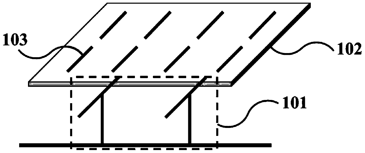
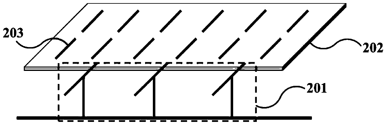
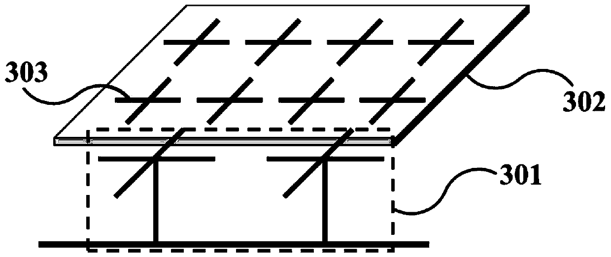
[0047] An antenna array with a new type of decoupling structure. A metasurface cladding is arranged above the antenna array. The metasurface cladding is supported by a dielectric support column and covers the antenna array. The metasurface cladding includes a dielectric substrate and is disposed on the dielectric substrate. The unit structure is used to adjust the dielectric constant. The equivalent dielectric constant of the metasurface coating is 15-45, and within this range, it can eliminate the coupling between antenna elements.

[0048] The existence of a metasurface coating with a high dielectric constant can introduce a new coupling path. By adjusting the dielectric constant and its size of the metasurface coating, the new coupling path can be made The transmitted wave and the original coupling wave between the antenna units cancel each other, thereby achieving the purpose of reducing the coupling. Two conditions need to be met to cancel each other out:

[0049] (1) Th...


PUM


Abstract

The invention discloses an antenna array with a novel decoupling structure. A metasurface coating layer is arranged above the antenna array, the metasurface coating layer is supported by a dielectricsupport column and covers the antenna array, the metasurface coating layer comprises a dielectric substrate and a unit structure arranged on the dielectric substrate, the unit structure is used for adjusting a dielectric constant, and an equivalent dielectric constant of the metasurface coating layer is 15-45. The dielectric constant of the metasurface coating layer is adjusted by adjusting a sizeand a spacing of the unit structure of the metasurface coating layer, and coupling between antenna units is eliminated by adjusting the size and the spacing of the unit structure of the metasurface coating layer and heights of the metasurface coating layer and the array antenna. Coupling among the units of the antenna array can be effectively reduced to 20 decibels or below 25 decibels, and radiation efficiency of the antenna units is improved by above 10%.

Description

technical field [0001] The invention belongs to the technical field of wireless communication, and in particular relates to a decoupling method of an antenna array and an antenna array with a novel decoupling structure, especially applicable to a multiple-input multiple-output (MIMO) system to improve the relationship between each antenna unit in the antenna array. The inter-coupling performance improves the isolation between units. Background technique [0002] With the rapid development of mobile communication systems, radio frequency spectrum resources are increasingly scarce. How to provide higher quality and faster communication services has become a research hotspot in the fifth generation mobile communication system (5G). In this context, the multiple-input multiple-output (MIMO) communication technology that has been proposed for a long time has become a key technology in the 5G system. [0003] Multiple-input multiple-output (MIMO) technology refers to using multip...

Claims


Application Information

Patent Timeline
Patent Type & Authority Applications(China)
IPC IPC(8): H01Q1/52H01Q1/36H01Q15/00H01Q21/00
CPCH01Q1/36H01Q1/523H01Q15/0026H01Q21/00
Inventor 赵鲁豫刘锋宋波
Owner XIAN LAMBDA COMM TECH CO LTD
Why Eureka
Try Eureka