Cyanogen chloride liquefaction and gas-liquid separation method

A technology of gas-liquid separation and gas-liquid separator, which is applied in the direction of separation methods, chemical instruments and methods, and dispersed particle separation, etc., which can solve the problems of small temperature interval, large amount of gasification, and more crystallization of the vessel wall, etc., so as to facilitate storage and the effect of measuring

Inactive Publication Date: 2020-05-26
THE RES INST FOR SPECIAL STRUCTURES OF AERONAUTICAL COMPOSITE AVIC
View PDF7 Cites 0 Cited by
  • Summary
  • Abstract
  • Description
  • Claims
  • Application Information

AI Technical Summary

Problems solved by technology

[0005] In view of the above-mentioned situation of the prior art, in order to overcome the gas, liquid and solid three-state temperature interval of cyanogen chloride is very small, too low temperature will cause many crystallizations on the device wall, and the problem of high gasification amount when the temperature is too high, the present invention The purpose is to provide a cyanogen chloride liquefaction and gas-liquid separation method to realize the liquefaction of most of the continuously produced high-temperature cyanogen chloride gas, and realize stable storage of liquid through low-temperature storage, which is beneficial to storage and measurement

Method used


Image

  • Cyanogen chloride liquefaction and gas-liquid separation method

Examples


Embodiment Construction

[0018] In order to understand the purpose, technical solution and advantages of the present invention more clearly, the method of the present invention will be further described in detail below in conjunction with the accompanying drawings and embodiments.

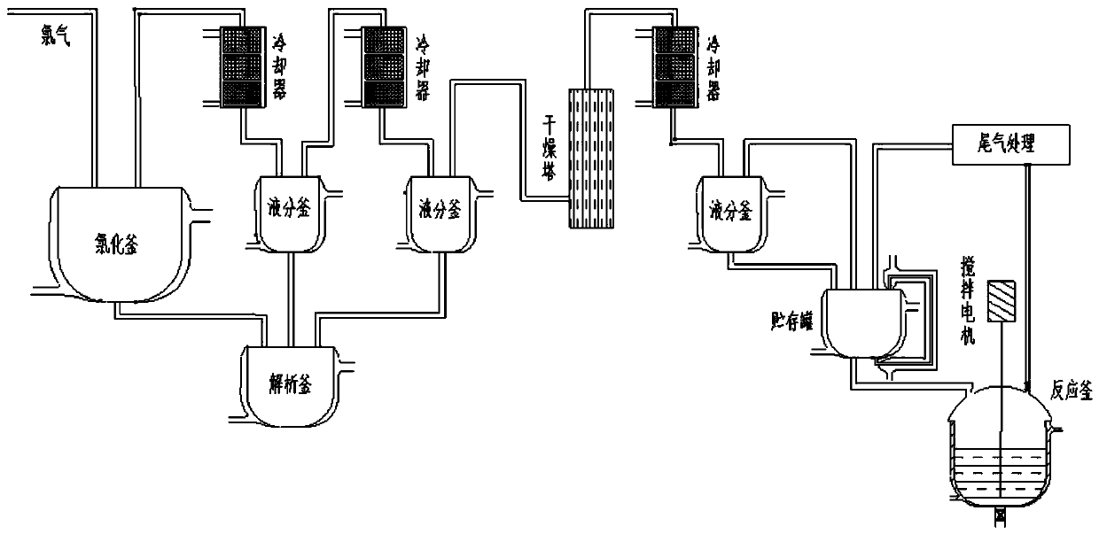
[0019] figure 1 It is the flowchart of the three-stage condensation-gas-liquid separation method of cyanogen chloride that the present invention is the present invention. Such as figure 1 Shown, the flow process of cyanogen chloride liquefaction and gas-liquid separation method of the present invention mainly comprises cyanogen chloride preparation, primary condensation, primary gas-liquid separation, secondary condensation, secondary gas-liquid separation, drying, tertiary condensation and The three-stage gas-liquid separation can also include the storage process of cyanogen chloride. Specific steps are as follows:

[0020] (1) Chlorine and sodium cyanide react in the chlorination reactor to prepare cyanogen chloride. ...


PUM


Abstract

The invention relates to a cyanogen chloride liquefaction and gas-liquid separation method, which comprises the following steps of: enabling high-temperature cyanogen chloride gas to sequentially passthrough a first-stage condenser and a first-stage gas-liquid separator to perform first-stage condensation and gas-liquid separation, setting the condensation temperature of the first-stage condenserto be -25 DEG C to -15 DEG C, enabling the mixed gas obtained after first-stage gas-liquid separation to sequentially pass through a second-stage condenser and a second-stage gas-liquid separator, conducting second-stage condensation and gas-liquid separation, setting the condensation temperature of the second-stage condenser to range from -25 DEG C to -15 DEG C, drying the mixed gas after the second-stage gas-liquid separation, enabling the dried mixed gas to sequentially pass through a third-stage condenser and a third-stage gas-liquid separator for third-stage condensation and gas-liquid separation, and setting the condensation temperature of the third-stage condenser to be -25 DEG C to -15 DEG C. Through three-stage condensation and three-stage gas-liquid separation processes, most ofcontinuously generated high-temperature cyanogen chloride gas can be liquefied, stable storage of liquid is achieved through low-temperature storage, and storage and metering are facilitated.

Description

technical field [0001] The invention belongs to the technical field of separation of chemical products, and in particular relates to a method for liquefying cyanogen chloride and separating gas and liquid. Background technique [0002] Cyanate resin is a new type of high-performance resin, which has excellent high temperature resistance, low and stable dielectric constant and dielectric loss tangent, low moisture absorption rate, small thermal expansion coefficient and good mechanical properties. It has extremely high application value in wave penetration / structural bearing. [0003] Cyanogen chloride is a commonly used intermediate raw material for the synthesis of cyanate resin monomers by the phenol-cyanogen halide method. Cyanogen chloride is generally synthesized by chlorine gas and sodium cyanide solution through the vapor phase method. After cyanogen chloride is generated, it is in a gas state, which is convenient for material flow and separation of impurities. It is...

Claims


Application Information

Patent Timeline
Patent Type & Authority Applications(China)
IPC IPC(8): B01D53/00B01D53/26
CPCB01D53/002B01D53/265B01D2257/2025B01D2257/80
Inventor 张明习轩立新王志强张志海
Owner THE RES INST FOR SPECIAL STRUCTURES OF AERONAUTICAL COMPOSITE AVIC
Why Eureka
Try Eureka