Grinding wheel manufacture method used for silicon wafer chamfering, and manufacture device

A manufacturing method and a manufacturing device technology, which are applied in the field of the grinding wheel manufacturing method and manufacturing device for chamfering of silicon wafers, can solve the problems of low precision of the cross-sectional shape of the grinding wheel groove, easy falling off of diamond abrasive grains, inconsistent groove shape and spacing, etc. , to achieve the effect of solving the problem that diamond abrasive particles are easy to fall off

Active Publication Date: 2020-06-05
SHENYANG POLYTECHNIC UNIV
View PDF12 Cites 0 Cited by
  • Summary
  • Abstract
  • Description
  • Claims
  • Application Information

AI Technical Summary

Problems solved by technology

[0010] Compared with the traditional grinding wheel manufacturing technology, the present invention proposes a grinding wheel manufacturing method and manufacturing device for chamfering silicon wafers, which effectively solves the problem that the diamond abrasive grains are easy to fall off in the traditional silicon wafer chamfering grinding wheel preparation method, and the cross-sectional shape of the grinding wheel groove The accuracy is not high, the groove shape and spacing are inconsistent, and the arc of the groove bottom is difficult to form problems

Method used


Image

  • Grinding wheel manufacture method used for silicon wafer chamfering, and manufacture device
  • Grinding wheel manufacture method used for silicon wafer chamfering, and manufacture device
  • Grinding wheel manufacture method used for silicon wafer chamfering, and manufacture device

Examples


Embodiment Construction

[0035] In order to make the object, technical solution and advantages of the present invention clearer, the present invention will be further described in detail below in conjunction with the accompanying drawings and embodiments. It should be understood that the specific embodiments described here are only used to explain the present invention, not to limit the present invention.

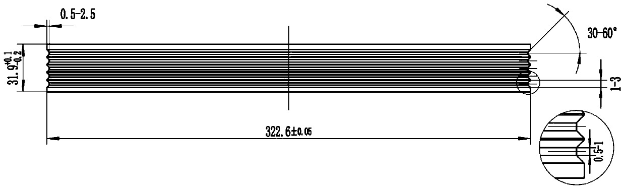
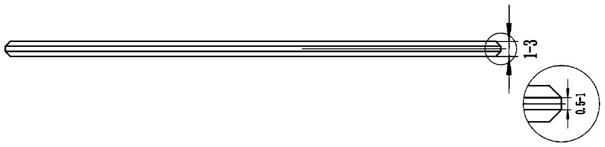
[0036] A method for manufacturing a grinding wheel for chamfering silicon wafers:

[0037] 1) Stir evenly the diamond powder with a particle size of 50-800 mesh and the Ti-Al-Cu-Sn metal powder at a volume concentration of 20%-95% to form the working layer powder of the grinding wheel; at the same time, the shape error is less than 10 Micron metal matrix, and put it into the metal mold; Next, inject the grinding wheel working layer powder into the annular cavity between the metal matrix and the metal mold, scrape it flat, and put it on the press for pressing, Form the compact on the surface of the...


PUM

PropertyMeasurementUnit
particle sizeaaaaaaaaaa
depthaaaaaaaaaa
angleaaaaaaaaaa

Abstract

The invention relates to a grinding wheel manufacture method used for silicon wafer chamfering, and a manufacture device. The manufacture method comprises the following steps of: 1) adopting a hot pressed sintering method to sinter and form a round-disk-shaped metal binding agent diamond grinding wheel; 2) adopting an electrosparking method to trim the outer cylindrical surface shape of the metalbinding agent diamond grinding wheel obtained by sintering; 3) adopting a rigid alloy rolling wheel with a specific shape to carry out rolling on the outer cylindrical surface of the diamond grindingwheel to obtain a trapezoid groove; and 4) adopting a working electrode which has the same shape with the rigid alloy rolling wheel to carry out electrosparking trimming on the trapezoid groove of thediamond grinding wheel. The device is provided with a rough machining rigid alloy rolling wheel, a finish machining rigid alloy rolling wheel, a diamond grinding wheel trimming working electrode anda grinding wheel groove trimming working electrode to independently manufacture and process the diamond grinding wheel. According to the grinding wheel manufacture method disclosed by the invention, the problems in a traditional grinding wheel manufacture method used for silicon wafer chamfering that diamond abrasive particles are likely to fall, the section shape of the grinding wheel groove is low in accuracy, the shape and the interval of the groove are inconsistent and a groove bottom circular arc is difficult to form can be solved.

Description

technical field [0001] The invention belongs to the field of precision machining, in particular to a method and device for manufacturing a grinding wheel for chamfering silicon wafers. Background technique [0002] With the development of economy and technology, monocrystalline silicon is used in more and more fields such as integrated circuits. The quality requirements for silicon wafers in these fields are also getting higher and higher. Silicon wafers are prone to various problems during transportation and use, such as defects such as chipping, cracks, and corners, which will cause a series of damage to subsequent surface processing and integrated circuit processes. In order to prevent defects in silicon wafers and increase the surface mechanical strength of the edge of silicon cutting wafers, eliminate edge cutting stress, reduce particle contamination, prevent edge cracking and particle shedding, silicon wafers should be chamfered. Silicon wafer chamfering is to trim ...

Claims


Application Information

Patent Timeline
Patent Type & Authority Applications(China)
IPC IPC(8): B24D18/00
CPCB24D18/0009B24D18/009
Inventor 苑泽伟王雪赵回回台立刚郎玲琪
Owner SHENYANG POLYTECHNIC UNIV
Why Eureka
Try Eureka