System used for vibration reduction and capable of changing structural rigidity

A technology of structural stiffness and magnetorheology, applied in the functional characteristics of spring/shock absorber, design features of shock absorber, spring/shock absorber, etc., can solve the problem of increasing design cost, component manufacturing cost, mold cost, installation and transportation cost and maintenance costs, the weak ability of the mechanical structure to resist vibration, and the non-universal working environment, etc., to achieve the effects of low cost, wide application range, and increased rigidity

Active Publication Date: 2020-06-12
SHANGHAI UNIV
View PDF5 Cites 1 Cited by
  • Summary
  • Abstract
  • Description
  • Claims
  • Application Information

AI Technical Summary

Problems solved by technology

In this case, if a high-strength, high-rigidity structure is adopted during manufacture, although it can resist vibration, it will also greatly increase the cost
If the strength and stiffness of the initial manufacturing structure are small, the mechanical structure itself has a weak ability to resist vibration and is easily damaged during the working process.
This is the shortcoming of the mechanical structure with invariable rigidity and strength, and the working environment is not universal. It is necessary to produce different corresponding mechanical structures according to the change of working conditions, which greatly increases the cost and the possibility of being damaged.
Take wind power generators as an example: the wind conditions are different from place to place, and even in different seasons and times in a geographical area, the magnitude, direction and duration of the wind are different, but if a variety of different models, blades and towers are produced accordingly type, will greatly increase the design cost, component manufacturing cost, mold cost, installation and transportation cost and maintenance cost, and also limit the promotion of wind turbines and the development of related technologies

Method used


Image

  • System used for vibration reduction and capable of changing structural rigidity
  • System used for vibration reduction and capable of changing structural rigidity
  • System used for vibration reduction and capable of changing structural rigidity

Examples


Embodiment 1

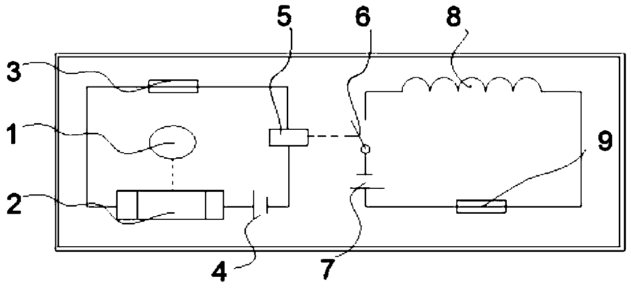
[0055] In this example, see Figure 1-Figure 4 . A system for damping vibration and capable of changing structural stiffness, including a control part, a current transmission part, and a magnetic flux sheet body;

[0056] The control part includes a sensor 1, a control unit 2, a relay 5, a control circuit power supply 4, and a control circuit fuse 3; the control unit 2, a control circuit power supply 4, a relay 5, and a control circuit fuse 3 are connected in series to form a control circuit; the sensor 1 The vibration test end is installed on the structural part to be detected, and the sensor 1 is a vibration sensor, which can perceive vibration signals;

[0057] The current transmission part includes a current transmission circuit power supply 7, a current transmission circuit fuse 9, and an electromagnetic rod 8, and forms a series current transmission series circuit. The corresponding switch 6 of the relay is arranged in the current transmission circuit, and can communica...

Embodiment 2

[0065] This embodiment is basically the same as Embodiment 1, especially in that:

[0066] In this example, if Figure 7 As shown, the system for reducing vibration and changing the structural rigidity of Embodiment 1 is installed on the tower of the wind power generator, the sensor 1 is installed on the tower structure body, and glued to the tower structure body by glue-free nails Surface; the control part is installed at the position 19 of the electric control board on the tower structure body; the current transmission part is installed at the device installation position 18 of the tower structure body, and energizes the electromagnetic rod 8.

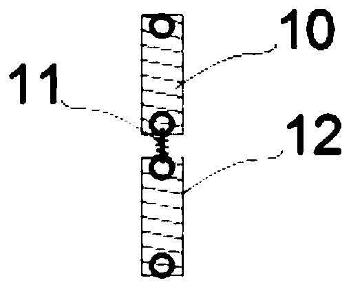
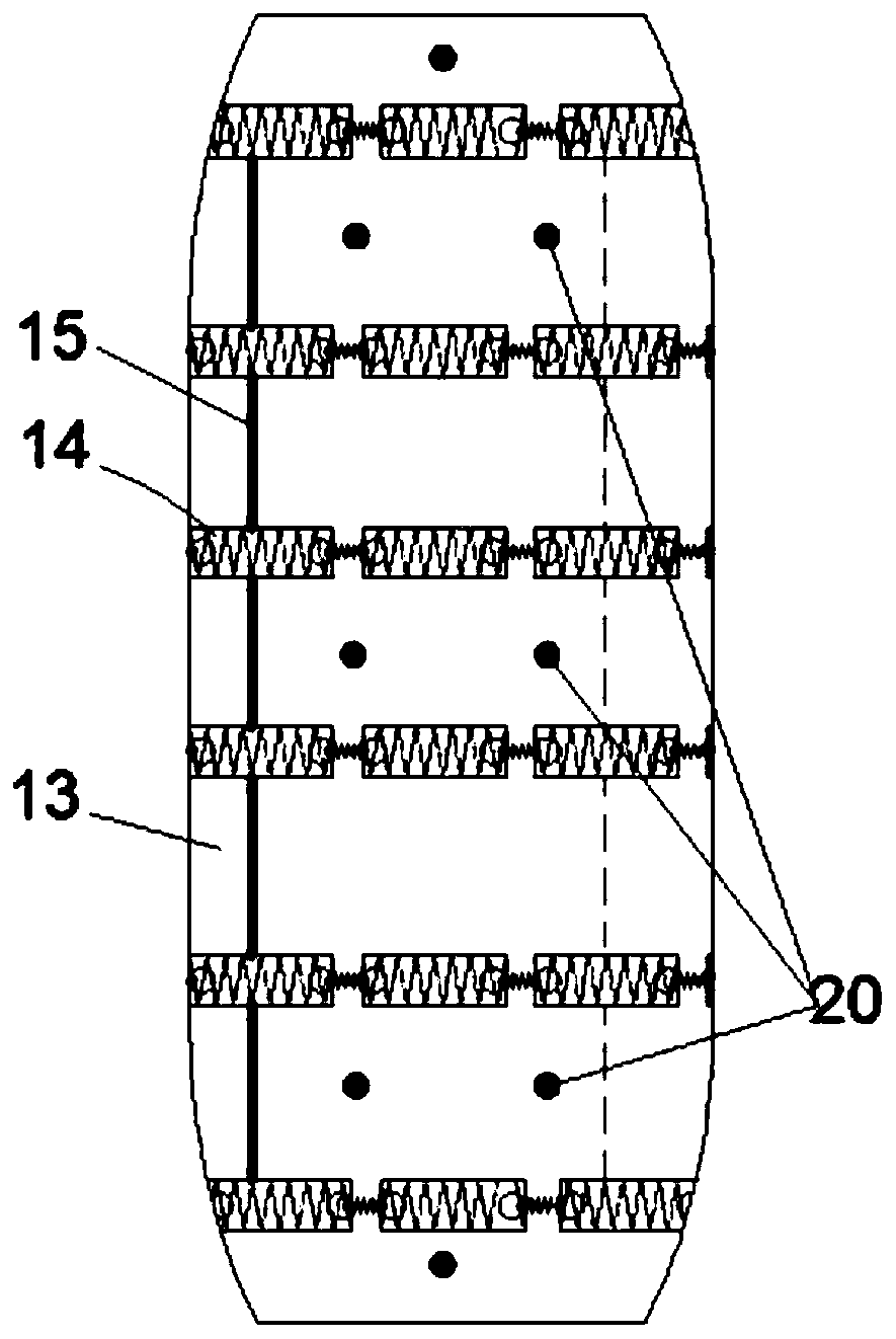
[0067] In this example, if Figure 5 with Image 6As shown, a mounting frame 16 is respectively provided near the two ends of the magnetorheological sheet 13, the magnetorheological sheet 13 is placed in the mounting frame 16, and the magnetorheological sheet 13 is pressed tightly. There are threaded holes 17 on the mounting frame ...

Embodiment 3

[0073] This embodiment is basically the same as the previous embodiment, and the special features are:

[0074] In this embodiment, the control unit 2 adopts an intelligent control algorithm to variably regulate the magnetic field applied to the corresponding magneto-rheological sheet 13 , so as to increase the stiffness of the structure as a whole or locally as required. The control process in the programmable control of the intelligent control algorithm is as follows:

[0075] First define the sliding mode function as s=B T Px, x is the velocity and displacement vectors of the lateral vibration and tangential vibration of the tower detected by the sensor; since the velocity and displacement are integral relations, that is, the time domain integral of velocity is the displacement, the other can be obtained from one quantity A quantity; where P is a 4th-order symmetric positive definite square matrix, the internal value of the P matrix is ​​designed using the linear inequalit...


PUM


Abstract

The invention discloses a system used for vibration reduction and capable of changing the structural rigidity. The system is divided into three main parts including a control part, a current transmission part and a magnetic current sheet body, wherein the control part comprises a vibration sensor, a control unit, a relay, a power supply and a fuse, the current transmission part comprises a power supply, a fuse, a relay corresponding switch and an electromagnetic rod, the magnetic current sheet body comprises magnetic conductive rubber and magnetorheological fluid arranged in the magnetic conductive rubber layer, the magnetic current sheet body is mounted and positioned on a tower drum through a mounting rack and an auxiliary mounting rack, and the electromagnetic rod is composed of an ironsheet, a metal spring and a wire and is transversely wound outside the magnetic current sheet body. When the electromagnetic rod is electrified, the electromagnetic rod discharges a magnetic field, the rigidity of the magnetic current sheet body is increased under the action of the magnetic field, and the solid property is shown; and the rigidity of the whole structure can be increased accordingto needs, and the change is rapid and reversible. According to the system, the magnetic field can be added by electrifying the system, so that the structural rigidity is improved, and the vibration and resonance problems are effectively solved.

Description

technical field [0001] The invention relates to an intelligent system device with a structure, in particular to an intelligent magnetorheological fluid device, which is applied in the technical fields of intelligent materials, intelligent structures and vibration reduction. Background technique [0002] With the continuous development of material science and control theory, intelligent systems of structures have been widely used. Because the working environment of many machines is complex and changeable, wind as a fluid, such as wind turbines, because its working environment is in the fluid, the direction and magnitude of the wind behave differently in different geographical environments and climate environments , and the wind has a sudden change, and the requirements for the structure of the wind turbine are very high. Therefore, how to implement better control of wind turbines and other mechanical devices with changing working environments has become a problem faced by ma...

Claims


Application Information

Patent Timeline
Patent Type & Authority Applications(China)
IPC IPC(8): F16F9/53F16F15/00F03D80/00
CPCF16F9/535F16F15/002F03D80/00F16F2230/08F16F2230/18F16F2228/066F16F2222/12F16F2224/045F16F2230/0041Y02E10/72
Inventor 常林闫恪涛于瀛洁郑维伟徐瞿磊王陈刘廷瑞孙涛
Owner SHANGHAI UNIV
Why Eureka
Try Eureka