Device for generating broadband chaotic laser

A chaotic laser, broadband technology, applied in the field of optical communication, can solve the problems of limitation, leakage of outer cavity length, limitation of effective bandwidth and flatness of power spectrum, etc., to improve security and anti-interference ability, improve distance resolution, spectrum High flatness effect

Active Publication Date: 2020-06-12
UNIV OF ELECTRONICS SCI & TECH OF CHINA
View PDF6 Cites 10 Cited by
  • Summary
  • Abstract
  • Description
  • Claims
  • Application Information

AI Technical Summary

Problems solved by technology

[0004] However, after in-depth research, scholars have found that there are some defects in the chaotic laser generated by the external cavity semiconductor laser: (1) The external cavity semiconductor laser has obvious relaxation oscillations. From the power spectrum, the main energy of the chaotic laser is concentrated in the relaxation Therefore, the effective bandwidth and flatness of the power spectrum are limited; (2) due to the existence of external cavity resonance, the autocorrelation curve of the generated chaotic signal has an obvious correlation peak at the external cavity period, which is called is a time-delay label; the existence of these defects limits the practical application
[0005] In secure communication, the relaxation oscillation causes the bandwidth of chaotic laser to be only a few GHz. This limited bandwidth will limit the transmission rate of chaotic optical communication; at the same time, the time delay characteristic leaks the length of the external cavity, which leads to the interception to use this key structural information. Reconstruct the chaotic carrier signal, and then crack the transmitted information, weakening the security of the communication system
In the generation of physical random numbers, the limited entropy source bandwidth limits the rate of generated physical random numbers; the delay characteristics deteriorate the randomness and equalization ratio of 0 and 1 bits, and need to be optimized by complex post-processing
In terms of radar detection, limited bandwidth limits the improvement of chaotic laser detection distance resolution; time delay characteristics also reduce the security and anti-interference ability of radar systems

Method used


Image

  • Device for generating broadband chaotic laser
  • Device for generating broadband chaotic laser
  • Device for generating broadband chaotic laser

Examples


Embodiment

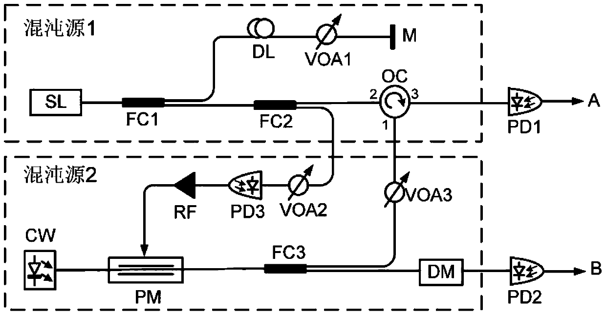
[0024] figure 1 It is a structure diagram of a specific embodiment of a device for generating broadband chaotic laser according to the present invention.

[0025] In this example, if figure 1 Shown, a kind of device of the present invention produces broadband chaotic laser, comprises:

[0026] Chaotic laser source 1 includes: semiconductor laser SL, fiber coupler FC, adjustable fiber delay line DL, optical circulator OC, fiber optic mirror M and adjustable optical attenuator VOA; in the present embodiment, semiconductor laser SL Choose distributed feedback laser DFB or vertical cavity surface emitting laser VCSEL;

[0027] Among them, the laser signal generated by the semiconductor laser SL is first divided into two channels by the fiber coupler FC1, and one of the laser signals is directly input to the adjustable optical delay line DL, and then passed through the adjustable optical delay line DL after delay processing by the adjustable optical delay line DL. The attenuator...


PUM


Abstract

The invention discloses a device for generating broadband chaotic laser, which is characterized in that chaotic laser output by a chaotic laser source 1 is divided into two paths: one path is converted into an electric domain chaotic signal by a photoelectric detector, and the electric domain chaotic signal is amplified by a radio frequency amplifier to be used as radio frequency input of a phasemodulator in a chaotic laser source 2; the other path is used as broadband chaotic laser finally generated by the chaotic laser source 1; a phase modulator output optical signal in the chaotic laser source 2 is also divided into two paths: one path is injected into a semiconductor laser in the chaotic laser source 1; and the other path passes through a dispersion module and then is used as broadband chaotic laser finally generated by the chaotic laser source 2.

Description

technical field [0001] The invention belongs to the technical field of optical communication, and more specifically relates to a device for generating broadband chaotic laser. Background technique [0002] Chaotic laser has important applications in the fields of secure optical communication, high-speed physical random number generation, and high-resolution anti-jamming radar detection. Using the wide-band and large-amplitude chaotic laser as the carrier wave to hide the information, and then using the chaos synchronization to demodulate the information, can realize the encrypted communication of high-speed information; because of its high bandwidth and large-amplitude noise-like characteristics, the chaotic laser is used as a new generation of physics The entropy source is used to solve the problem of insufficient real-time generation rate of physical random numbers; the radar system is constructed by using broadband chaotic laser as a signal source, which can effectively i...

Claims


Application Information

Patent Timeline
Patent Type & Authority Applications(China)
IPC IPC(8): H04B10/85H04L9/00H04L9/08
CPCH04B10/85H04L9/001H04L9/0869
Inventor 江宁赵安可邱昆
Owner UNIV OF ELECTRONICS SCI & TECH OF CHINA
Why Eureka
Try Eureka