
Method for removing heavy metals in sludge

A technology for heavy metals and sludge, applied in sludge treatment, biological sludge treatment, chemical instruments and methods, etc., can solve the problem of low removal efficiency of heavy metals, and achieve the goal of facilitating the migration of heavy metals, strong reproductive capacity, and reducing the amount of precipitation. Effect

Inactive Publication Date: 2020-06-19
江西浩德实业有限公司 +1
View PDF10 Cites 2 Cited by
  • Summary
  • Abstract
  • Description
  • Claims
  • Application Information

AI Technical Summary

Problems solved by technology

[0003] In view of the above defects or improvement needs of the prior art, the present invention provides a method for removing heavy metals in sludge, by combining electrodynamics and leaching to treat heavy metal sludge, the removal rate of heavy metals in sludge is improved, thereby Solve the technical problem of low removal efficiency of heavy metals in sludge in the prior art

Method used


Image

  • Method for removing heavy metals in sludge
  • Method for removing heavy metals in sludge
  • Method for removing heavy metals in sludge

Examples


Embodiment 1

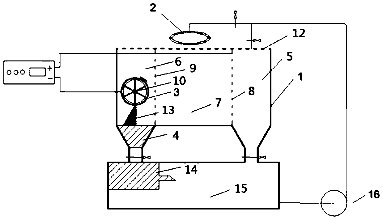
[0049] A method for removing heavy metals in sludge, such as figure 1 shown, including the following steps:

[0050] 1. Sludge acidification pretreatment: crush the industrial sludge with a heavy metal Cd content of 544.61mg / kg, add deionized water according to the mass ratio of deionized water to sludge dry matter 3:1, stir evenly, and then add to the sludge Add a certain amount of dilute nitric acid to adjust the pH of the sludge to 6, and balance for 8 hours.

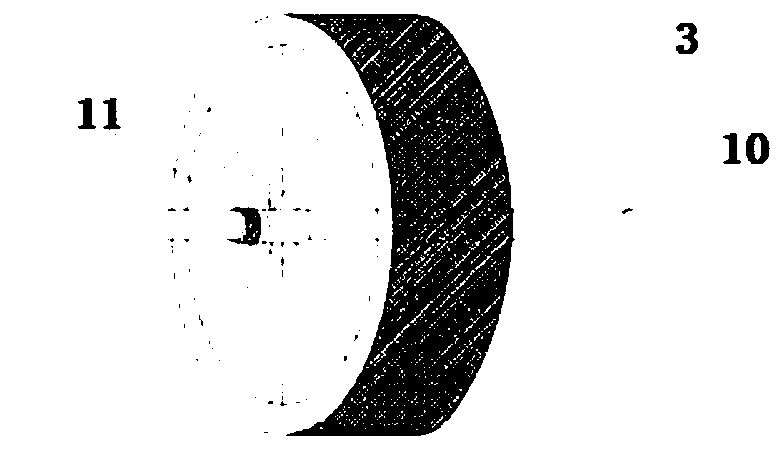
[0051] 2. Electric-leaching repair: Assemble the electrolysis device, such as figure 2 As shown, the electrolysis device includes an anode chamber 5, a cathode chamber 6 and a sludge chamber 7; the anode chamber 5 and the sludge chamber 7 are separated by an anode plate 8, and the surface of the anode plate 8 has a hole structure; the cathode The chamber 6 and the sludge chamber 7 are separated by a partition 9, and the surface of the partition 9 has a hole structure; the cathode 3 is located in the cathode chambe...

Embodiment 2

[0057] 1. Sludge acidification pretreatment: crush the industrial sludge with a heavy metal Cu content of 3504.63mg / kg, add deionized water according to the mass ratio of deionized water to sludge dry matter 3:1, stir evenly, and then add to the sludge Add a certain amount of dilute nitric acid to adjust the pH of the sludge to about 5, and balance for 8 hours.

[0058] 2. Electric-leaching repair: use the electric washing device in Example 1 to treat for 6 hours and then cut off the power, use the Tessier five-step extraction method to measure the form of heavy metals in the treated sludge, and the measured Cu residue state is changed from the initial 782.41mg / kg decreased to 250.03mg / kg, while the carbonate binding state increased from 530.56mg / kg to 1031.22mg / kg.

[0059] 3. Bioremediation: Mix the sludge obtained in step 2 with ordinary soil at a mass ratio of 2:3, apply an appropriate amount of water, and plant an appropriate amount of bermudagrass seedlings. After the t...


PUM


Abstract

The invention belongs to the fields of treatment and disposal of sludge containing heavy metals in environmental protection, and more specifically relates to a method for removing heavy metals in sludge. The method comprises the following steps: acidifying the sludge containing heavy metals, adjusting the pH of the sludge to be weakly acidic, then carrying out balancing for at least 5 hours, thenplacing treated sludge into a sludge chamber of a sludge electrolysis device, adding organic acid serving as an eluting agent into the sludge chamber, allowing the eluting agent to be combined with heavy metals in the sludge in the sludge chamber through a desorption, dissolution or complexation effect under the action of an electric field so as to form a transferable compound to move towards a cathode chamber, and allowing the sludge to migrate out under the action of an electrodynamic force so as to obtain the sludge repaired through electric elution. The method provided by the invention canimprove the removal rate of the heavy metals in the sludge.

Description

technical field [0001] The invention belongs to the field of treatment and disposal of sludge containing heavy metals in environmental protection, and more specifically relates to a method for removing heavy metals in sludge. Background technique [0002] The remediation technology of sludge containing heavy metals mainly has the following methods: (1) Bioleaching is to transfer the heavy metals in the sludge to the liquid phase under acidic conditions, and then separate the solid and liquid to obtain clean sludge, which is the current effect A better treatment method, but it takes a long time, usually 8-10 days, and the process conditions are strict, and the presence of heavy metals will also have a toxic effect on the leaching microorganisms. (2) The chemical oxidation remediation technology mainly uses the oxidation of chemical agents to transform the pollutants in the sludge into low-toxic forms through chemical reaction changes, so as to reduce the environmental risk of...

Claims


Application Information

Patent Timeline
IPC IPC(8): C02F11/00C02F11/02C02F11/15C02F101/20
CPCC02F11/00C02F11/02C02F2101/20C02F11/15
Inventor 杨华荣吴旭邢思奇李佳旭
Owner 江西浩德实业有限公司
Learn More