Real-time stress monitoring system and safety coefficient detection method for coupling bolt

A technology of stress monitoring and axial stress, which is applied in general control systems, control/regulation systems, force/torque/power measuring instruments, etc., can solve problems such as abnormal vibration of units, reduction of equipment life, fatigue damage of fasteners, etc. Achieve the effect of low environmental requirements, improve work efficiency and reduce workload

Active Publication Date: 2020-06-23
DONGFANG ELECTRIC MACHINERY
View PDF20 Cites 4 Cited by
  • Summary
  • Abstract
  • Description
  • Claims
  • Application Information

AI Technical Summary

Problems solved by technology

The aforementioned technical scheme can achieve the relationship between residual stress and hardness by changing the residual stress loading at a certain temperature; it can also achieve a certain residual stress loading and obtain the relationship between residual stress and hardness by changing the temperature; but its implementation is If conditions permit, the temperature needs to be controlled and cannot be monitored in real time
However, the working status of the coupling bolts and other fasteners of the hydro-generator set is crucial to the safe and stable operation of the entire unit. Reduced connection reliability, fatigue damage of fasteners and reduced shafting stability, and even induce abnormal vibration of the unit, affect the normal economical, safe and stable operation of the unit, and reduce the life of the equipment. Therefore, the coupling bolts of the hydro-generator set It is necessary to implement online monitoring and real-time safety assessment of fasteners

Method used


Image

  • Real-time stress monitoring system and safety coefficient detection method for coupling bolt
  • Real-time stress monitoring system and safety coefficient detection method for coupling bolt
  • Real-time stress monitoring system and safety coefficient detection method for coupling bolt

Examples


Embodiment 1

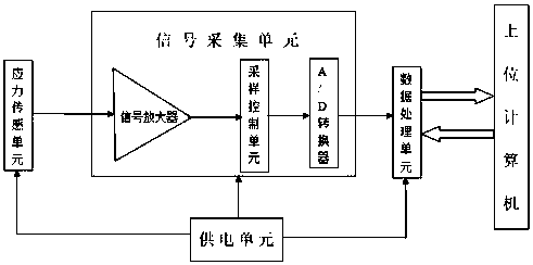
[0075] The invention discloses a real-time stress monitoring system for shaft coupling bolts. As a basic embodiment of the invention, it includes a hydroelectric generator set, a power supply unit, a stress sensing unit, a signal sampling unit, a data processing unit and a host computer; The hydroelectric generating set includes the coupling bolt body and the turbine cover; the power supply unit is arranged inside or outside the turbine cover, and is respectively connected to the stress sensing unit, signal sampling unit and data processing unit through wires; the stress sensing unit includes Several stress sensors, the stress sensor is set on the coupling bolt body, connected to the signal sampling unit through wires; the signal sampling unit is set on the inside or outside of the turbine cover, including signal amplifier, sampling control unit and A / D converter ; The signal input end of the sampling control unit is connected with the stress sensing unit through the signal amp...

Embodiment 2

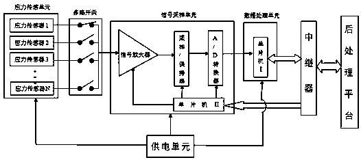
[0078]The invention discloses a real-time stress monitoring system for shaft coupling bolts. As a preferred embodiment of the invention, that is, in Example 1, a wireless data connection is adopted between the data processing unit and the upper computer; the data processing unit and the upper computer A repeater is arranged between them; the sampling control unit includes a single-chip microcomputer II and a sample / hold device; a multi-way switch is arranged between the stress sensing unit and the signal amplifier.

[0079] The performance of the signal sampling unit depends on the sampling accuracy and sampling speed. Under the condition of ensuring that the signal sampling unit has sampling accuracy, there is as high a sampling speed as possible to meet the requirements of real-time processing and control. Therefore, this technical solution adopts a program-controlled data sampling system, that is, a single-chip microcomputer is added to the data sampling control unit Ⅱ. Rea...

Embodiment 3

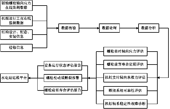
[0081] The invention discloses a method for detecting the safety factor of coupling bolts, as a basic embodiment of the invention, including preliminary preparation, data collection, data processing, data call and display;

[0082] Preliminary preparation refers to the logic control program written into the data processing unit through the upper computer, including the real-time axial stress evaluation program of bolts, the fatigue life evaluation program of coupling bolts, the real-time axial water thrust evaluation program of the unit, and the reliability evaluation program of the connection system , Shafting stability fault diagnosis program, and set the bolt real-time axial stress amplitude alarm threshold and bolt fatigue damage alarm threshold;

[0083] Real-time axial stress evaluation of bolts: When the bolts are well pre-tightened, based on the online monitoring stress of the bolts and the real-time working condition data of the unit, the real-time stress state of the ...


PUM


Abstract

The invention relates to the field of stress monitoring of coupling bolts, and discloses a real-time stress monitoring system and a safety coefficient detection method for a coupling bolt. The monitoring system mainly comprises a stress sensing unit arranged on a coupling bolt body, and a signal sampling unit, a power supply device and a data processing unit which are arranged on the inner side orthe outer side of a water turbine protective cover. Based on the monitoring system, a logic control program is written into the data processing unit through the upper computer, so that the data processing unit has the capacity of calculating, judging and analyzing received signals, and then the data processing unit is accessed through the upper computer. According to the technical scheme, the axial stress of the bolt on the rotating part of the water turbine generator set and the axial hydraulic thrust of the water turbine can be monitored in real time. Meanwhile, the reliability of a rotating connection system and the fatigue life of the connection bolt can be evaluated regularly, and quantitative and qualitative scientific bases are provided for safe operation, scientific maintenance and fault diagnosis of a power station.

Description

technical field [0001] The invention relates to the field of stress monitoring of coupling bolts, in particular to a real-time stress monitoring system and safety factor detection method of coupling bolts. Background technique [0002] Fasteners such as bolts and studs have been widely used in railways, bridges, hydropower, wind power, nuclear power, transportation, aerospace and other fields. Due to their complex and diverse working environments, they usually need to withstand large impact loads, temperature changes and Corrosion and other unfavorable factors, these unfavorable factors are likely to cause joint failure problems such as bolt looseness or fracture, therefore, early detection of defects in fixing parts and real-time working stress of bolts are of great significance to ensure the safe operation of equipment and improve equipment life. . [0003] The effectiveness of fastener joints is very important, and the stress state of their work can reflect whether they ...

Claims


Application Information

Patent Timeline
Patent Type & Authority Applications(China)
IPC IPC(8): G01L5/24G05B19/042
CPCG01L5/246G05B19/0423
Inventor 张猛郭靖杜芝鹏
Owner DONGFANG ELECTRIC MACHINERY
Why Eureka
Try Eureka