Active metal cutting chip breaking method and active metal cutting chip breaking device for unmanned workshop

A metal cutting, active technology, applied in metal processing equipment, turning equipment, auxiliary devices, etc., can solve the problems of increasing pretreatment machining allowance, chip breaking, tool impact, etc., and achieve the effect of stable chip breaking effect.

Inactive Publication Date: 2020-07-10
NANJING UNIV OF TECH
View PDF4 Cites 1 Cited by
  • Summary
  • Abstract
  • Description
  • Claims
  • Application Information

AI Technical Summary

Problems solved by technology

One is the setting of the modification depth; if the depth is too deep, the preprocessing allowance will be increased; and, if the depth is greater than the cut...

Method used


Image

  • Active metal cutting chip breaking method and active metal cutting chip breaking device for unmanned workshop
  • Active metal cutting chip breaking method and active metal cutting chip breaking device for unmanned workshop
  • Active metal cutting chip breaking method and active metal cutting chip breaking device for unmanned workshop

Examples


Embodiment 1

[0038] Embodiment one is a method embodiment.

[0039] The parts processed in this embodiment have three different diameter variations, which are 30 mm, 26 mm and 24 mm respectively from left to right.

[0040] Step (a).

[0041] To turn the part, three cutting passes are performed. The depth of cut and workpiece diameter variation for each pass is shown in the table below. The three tool passes maintain the same spindle speed of 300r / min and feed rate of 0.02mm / rev.

[0042]

[0043] Step (b).

[0044] According to the cutting elements and conditions obtained in step (a), the trajectory of each cutting tool of the turning tool is determined.

[0045] Step (c).

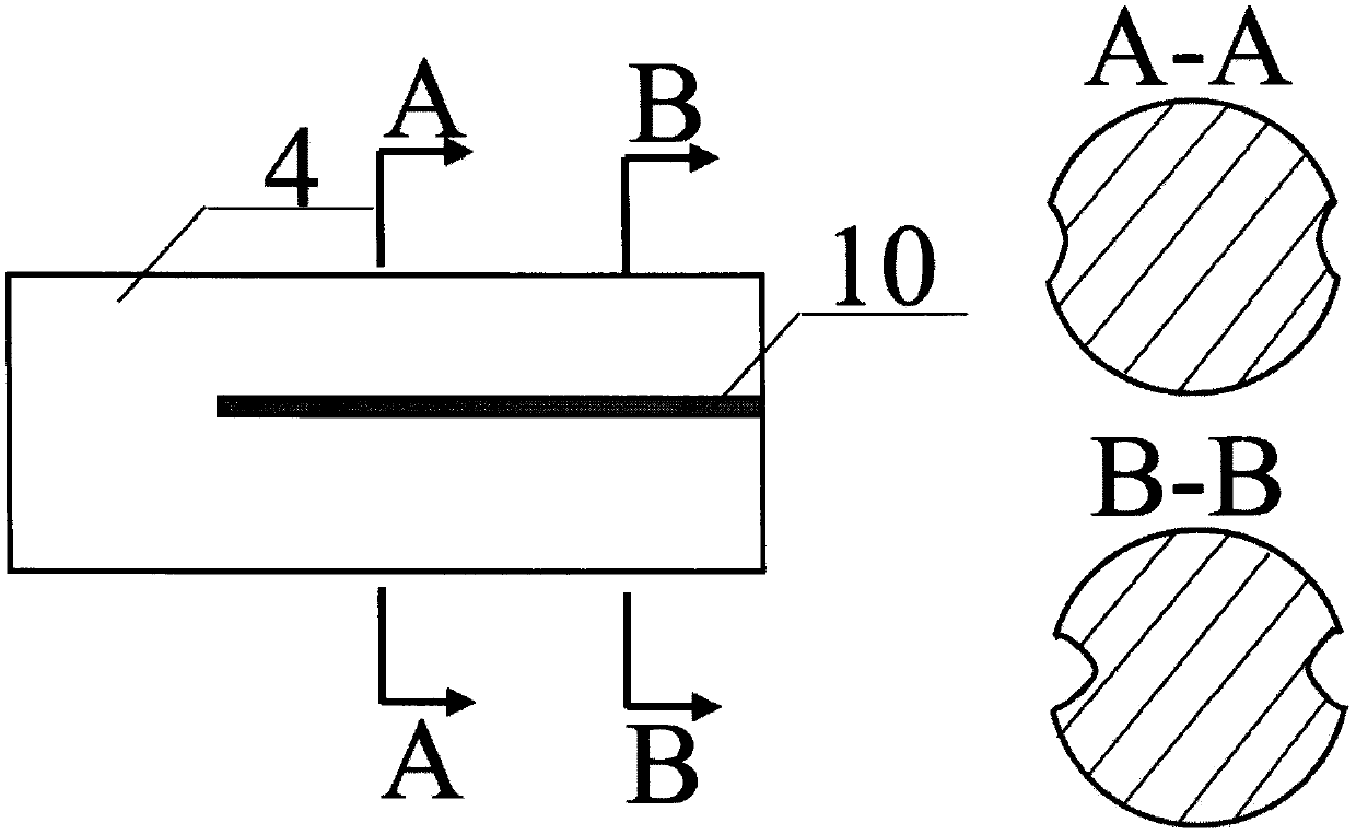
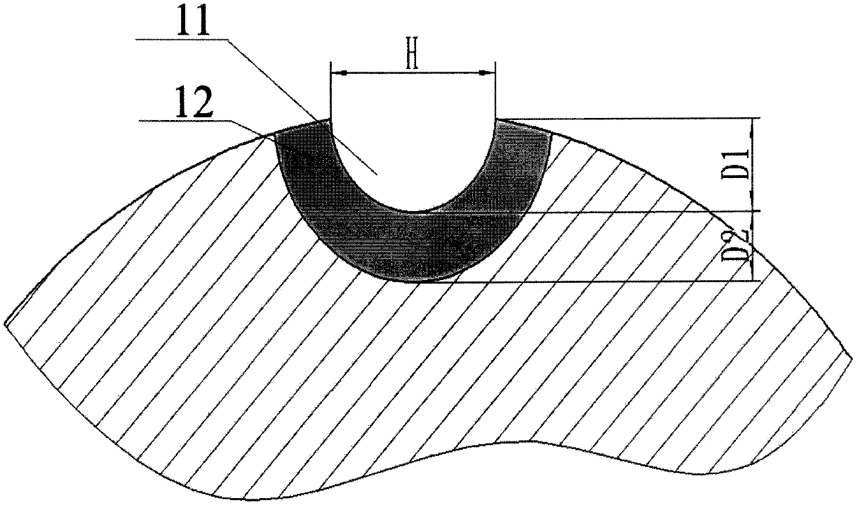
[0046] Before the first tool pass, the surface pretreatment topography is processed on the surface of the workpiece. The appearance of the topography is a groove shape, and the direction is parallel to the axial direction of the workpiece, such as Figure 1 shown. Depending on the depth of cut, the grooves h...

Embodiment 2

[0055] The second embodiment is a device embodiment.

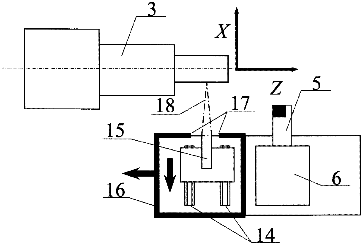
[0056] The parts processed in this embodiment have three different diameter variations, which are 30 mm, 26 mm and 24 mm respectively from left to right. The working principle of the device is as image 3 and Figure 4 shown.

[0057] The device in this embodiment includes a laser module 15 , a mechanical module, an air blowing module and a protective cover 16 .

[0058] The high-energy beam module modifies and pre-treats the workpiece surface by outputting high-energy beams.

[0059] The mechanical module realizes the motion function of the device. The output end of the high-energy beam module is fixed on the X-direction slide rail 14, which has a sliding function in the X-axis direction of the lathe; the horizontal guide rail is fixed on the tool rest. With the above structure, the distance between the output end of the high-energy beam module and the surface of the workpiece is kept constant.

[0060] A protective...


PUM


Abstract

The invention relates to an active metal cutting chip breaking method and an active metal cutting chip breaking device for an unmanned workshop. The core concept of the active chip breaking method lies in that surface transformation and modification pretreatment is carried out in a special position of the surface of a workpiece before a tool is fed to cut every time. When the tool cuts to a pretreatment position, thickness or material characteristics of newly born chips on the surface of a workpiece changes suddenly, so that breakage is achieved. The principle of the active chip breaking device lies in that a material of the workpiece is gasified by applying a high energy laser beam to form a trench, and meanwhile, the characteristics of the material of the workpiece is changed by means ofthe heat effect of the laser beam, so that a heat influence area of a certain depth is formed. The device is provided with a high energy laser module, and a high energy laser output end is fixed to ahorizontal guide rail, so that the device has a translational function in the x-axis direction of a lathe. The horizontal guide rail is fixed to a knife rest. According to the structure, the focusingposition of the laser beam can change along with diameter change of the workpiece. Matched with movement of the knife rest in the z-axis direction of the knife rest, surface transformation and modification pretreatment on the surface of the workpiece is achieved. Compared with a chip breaking slot of the tool, the method and device are more stable and reliable in effect. Compared with high pressure water/gas jet chip breaking, the method and device are lower in energy consumption and cost and are further more environment-friendly.

Description

[0001] Technical field [0002] The invention relates to an active chip breaking method and device for unmanned workshops in metal cutting processing, belonging to the fields of mechanical manufacturing technology and metal cutting processing. Background technique [0003] Continuous metal cutting often encounters the problem of poor chip breaking. The entanglement and entrainment of chips will not only damage the machined flat surface of the workpiece, but also aggravate the wear of the tool; in severe cases, it may even cause damage to the machine tool and injury to personnel. In order to avoid excessively long and entangled chips, it is often necessary to manually monitor the cutting state or install a chip detection device; however, the above measures cannot completely eliminate the hidden dangers caused by insufficient chip breaking. Therefore, at present, in the process of processing high plasticity metal materials such as aluminum alloy and titanium alloy, it is still ...

Claims


Application Information

Patent Timeline
IPC IPC(8): B23B25/02
CPCB23B25/02
Inventor 康正阳苏小平周大双杨宇骄刘澄成刘锐鹿盈盈缪小冬
Owner NANJING UNIV OF TECH
Why Eureka
Try Eureka