Carbon fiber and metal composite structure and preparation method thereof

A metal composite structure and carbon fiber technology, which is applied in the direction of metal layered products, chemical instruments and methods, and synthetic resin layered products, can solve the problem of affecting the reinforcement effect of aramid fiber reinforced carbon fiber and metal composite structures, and reduce the carbon fiber and metal composite structure. Structural bonding strength, adhesive viscosity and other problems, to achieve the effect of blocking galvanic corrosion, increasing surface roughness, and improving fatigue life

Inactive Publication Date: 2020-07-10
CHANGAN UNIV
View PDF4 Cites 4 Cited by
  • Summary
  • Abstract
  • Description
  • Claims
  • Application Information

AI Technical Summary

Problems solved by technology

Due to the high viscosity and insufficient fluidity of the adhesive, the adhesive cannot completely penetrate into the inside of the aramid fiber and the very small pits or gaps on the metal surface, and pores will be formed in the adhesive layer and the inside of the aramid fiber. There are gaps on the metal surface, and the adhesive is brittle after curing and is sensitive to defects. Therefore, these gaps and pores will reduce the bonding strength of the carbon fiber and metal composite structure
If the metal surface is sandblasted, since the diameter of the aramid fiber is basically the same as the size of the pit on the sandblasted metal surface, the number of aramid fibers embedded in the rough metal surface is limited, which will directly affect the aramid fiber reinforced carbon fiber and metal composite structure Enhanced effect of

Method used


Image

  • Carbon fiber and metal composite structure and preparation method thereof
  • Carbon fiber and metal composite structure and preparation method thereof
  • Carbon fiber and metal composite structure and preparation method thereof

Examples


Embodiment Construction

[0029] The present invention is described in further detail below in conjunction with accompanying drawing:

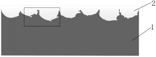
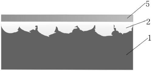
[0030] The present invention optimizes the carbon fiber and metal composite structure, and the specific metal can be steel or other alloy materials. In this embodiment, steel is taken as an example, and the steel surface is subjected to shot blasting or shot blasting treatment, causing the crystal lattice on the steel surface to be distorted and deformed. Form a plastic deformation layer on the steel surface, increase the hardness of the steel surface, and form a steel surface with a surface roughness several times the diameter of the aramid short fiber 4, increase the number of aramid short fiber 4 embedded in the rough steel surface, and strengthen the carbon fiber / steel The strength of the composite structure prolongs the service life of the composite structure. Due to the continuous impact of high-speed pellets on the steel surface, the crystal structure is distort...


PUM

PropertyMeasurementUnit
tensile strengthaaaaaaaaaa
elastic modulusaaaaaaaaaa
strengthaaaaaaaaaa

Abstract

The invention discloses a preparation method of a carbon fiber and metal composite structure, which comprises the following steps: 1. carrying out shot blasting or shot penning treatment on the bonding surface of metal at least once to form roughened metal; 2, spraying an acetone resin solution on the surface of the rough metal, and carrying out pretreatment; 3, coating the surface of the pretreated rough metal with a binder; 4, carrying out infiltration treatment on an aramid short fiber film by using an acetone resin solution, and placing the aramid short fiber film on the rough metal surface; and 5, carrying out infiltration treatment on carbon fiber cloth by using an acetone resin solution, coating the surface of the carbon fiber cloth with a binder, covering the rough metal surface treated in the step 4 with the carbon fiber cloth, and carrying out static pressing until the carbon fiber and metal composite structure is cured and molded. Joint reinforcement of two interface layersbetween metal and a binder and between carbon fibers and the binder and a binder layer is realized.

Description

technical field [0001] The invention belongs to the field of composite materials, and relates to a carbon fiber and metal composite structure and a preparation method thereof. Background technique [0002] Due to its high strength, uniform material, stable quality, good plasticity and toughness, easy construction and easy maintenance, metal structures are more and more used in various fields. Carbon Fiber Reinforced Polymer, referred to as CFRP, not only has the advantages of high strength, high elastic modulus, light weight, strong corrosion resistance, good fatigue performance and good shock absorption performance, but also can maximize the self-weight of reinforced components. The carbon fiber-metal composite structure has been widely used in civil engineering, aviation, aerospace, automobile, petroleum industry and other fields without substantial increase, cross-sectional size and appearance of reinforced components will not change significantly. [0003] In order to i...

Claims


Application Information

Patent Timeline
Patent Type & Authority Applications(China)
IPC IPC(8): B32B7/12B32B9/00B32B9/04B32B15/14B32B27/02B32B27/34B32B27/06B32B27/12B32B33/00B32B37/10B32B37/12B32B38/00
CPCB32B5/02B32B5/26B32B7/12B32B15/14B32B9/047B32B27/06B32B27/12B32B33/00B32B38/0012B32B37/1284B32B37/10B32B2255/06B32B2255/26B32B2260/021B32B2260/046B32B2262/0269B32B2262/106B32B2307/552B32B2307/206B32B2307/20B32B2307/728B32B2307/558
Inventor 王斌华康思思
Owner CHANGAN UNIV
Why Eureka
Try Eureka