Clock data recovery method and circuit

A clock data recovery and circuit technology, applied in the field of network communication, can solve problems such as phase jitter amplification, achieve the effect of reducing spurs, wide frequency coverage, and realizing fractional frequency division

Pending Publication Date: 2020-07-14
ZHONGXING LIANHUA TECH BEIJING CO LTD
View PDF7 Cites 3 Cited by
  • Summary
  • Abstract
  • Description
  • Claims
  • Application Information

AI Technical Summary

Problems solved by technology

In this way, since the network signal is regenerated by the CDR circuit, its phase jitter will be amplified

Method used


Image

  • Clock data recovery method and circuit
  • Clock data recovery method and circuit
  • Clock data recovery method and circuit

Examples


Embodiment Construction

[0036] The specific embodiments of the present invention will be further described below in conjunction with the accompanying drawings. The following examples are only used to illustrate the technical solution of the present invention more clearly, but not to limit the protection scope of the present invention.

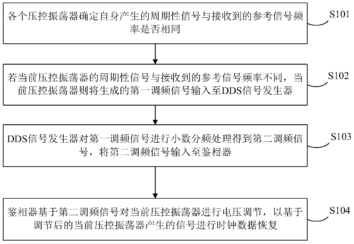
[0037] figure 1 It shows a schematic flowchart of a clock data recovery method provided in this embodiment, including:

[0038] S101. Each voltage-controlled oscillator determines whether the frequency of the periodic signal generated by itself is the same as that of the received reference signal.

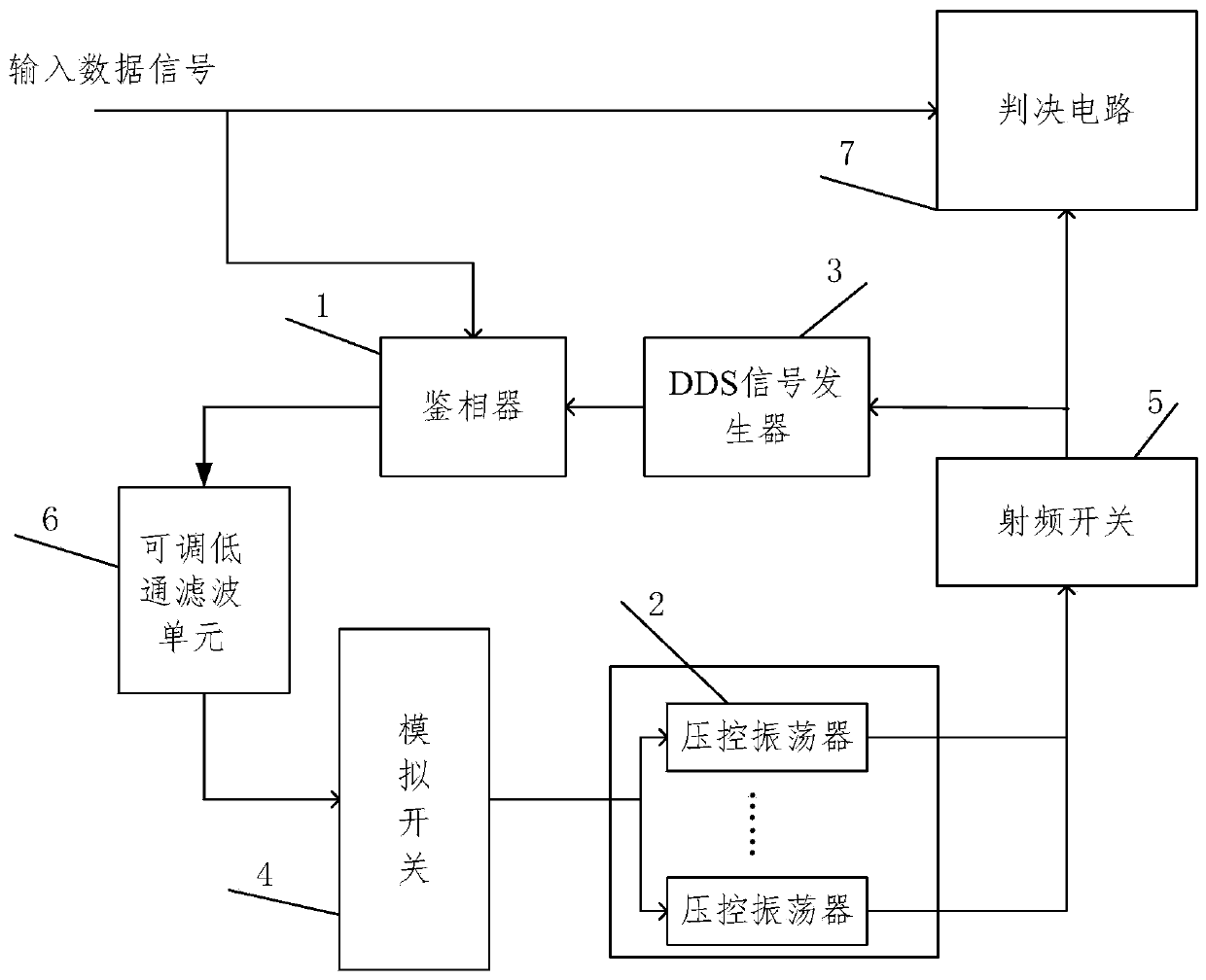
[0039] In implementation, the phase detector can adjust the voltage of the voltage-controlled oscillator according to the frequency modulation signal generated by each voltage-controlled oscillator (at least two) based on the periodic signal generated by itself and the received reference signal, so as to be based on the The signal generated by the regulated voltage-contr...


PUM


Abstract

An embodiment of the invention discloses a clock data recovery method and a clock data recovery circuit. The clock data recovery method comprises the following steps: each voltage-controlled oscillator determines whether the frequency of a periodic signal generated by the voltage-controlled oscillator is the same as that of a received reference signal; if the frequency of the periodic signal of the current voltage-controlled oscillator is different from that of the received reference signal, the current voltage-controlled oscillator inputs the generated first frequency modulation signal to a DDS signal generator; the DDS signal generator performs fractional frequency division processing on the first frequency modulation signal to obtain a second frequency modulation signal, and inputs thesecond frequency modulation signal to the phase discriminator; the phase discriminator performs voltage regulation on the current voltage-controlled oscillator based on the second frequency modulationsignal so as to perform clock data recovery based on the regulated signal generated by the current voltage-controlled oscillator. According to the method disclosed in the invention, high-speed clockdata recovery can be realized, the quality of recovered clock signals is improved, and wide-frequency coverage can be realized.

Description

technical field [0001] The invention relates to the technical field of network communication, in particular to a clock data recovery method and circuit. Background technique [0002] With the continuous development of network communication technology, the transmission distance and transmission speed of the backbone network are also increasing. In order to ensure the efficient transmission of network data, how to realize the recovery of the clock signal and the data signal becomes particularly important. [0003] At present, a clock signal and a data signal are recovered by using a CDR (Clock and Data Recovery, high-speed clock data recovery) circuit. Specifically, the CDR circuit includes two parts: a clock recovery (CR, Clock Recovery) circuit and a data recovery (DR, Data Recovery) circuit, and DR can be subdivided into a clock data phase adjustment (phase alignment, phase alignment) circuit and a data sampling circuit. decision circuit. When performing long-distance hi...

Claims


Application Information

Patent Timeline
Patent Type & Authority Applications(China)
IPC IPC(8): H03L7/18
CPCH03L7/18
Inventor 尹项托龚胜民
Owner ZHONGXING LIANHUA TECH BEIJING CO LTD
Why Eureka
Try Eureka