Negative pressure waste gas discharge disinfection sterilizer and manufacturing method thereof

A technology for disinfection and sterilizers and exhaust gas discharge, which is applied to chemical instruments and methods, separation methods, manufacturing tools, etc., and can solve the problems of difficult welding of protective covers and increase the pressure bearing capacity of protective covers, etc.

Active Publication Date: 2021-04-20
ZHEJIANG QIANGSHENG MEDICAL ENG
View PDF5 Cites 0 Cited by
  • Summary
  • Abstract
  • Description
  • Claims
  • Application Information

AI Technical Summary

Problems solved by technology

In the manufacturing method, the angle between the two side plates can be controlled, and at the same time, the end plate can be welded between the two side plates that define the angle, and the welding position of the side plate and the end plate can be set inside the side plate and the end plate The contact point can avoid the welding part from being damaged, and the side plate can be cut according to the end plate, so that the designed protective cover in the shape of a prism can be obtained, which solves the technical problem that the inside of the protective cover in the shape of a prism is not easy to weld; at the same time, it can The inner cavity is kept inside the protective cover, and the support plate is welded to the inner cavity and the end plate, which not only solves the connection between the inner cavity and the protective cover, but also increases the vertical pressure bearing capacity of the protective cover, which is convenient in the The heating element is vertically installed in the shell; and through the elastic deformation of the spring, the side plate fixing rod used to fix the side plate reciprocates, and the protective cover can be obtained by batch welding

Method used


Image

  • Negative pressure waste gas discharge disinfection sterilizer and manufacturing method thereof
  • Negative pressure waste gas discharge disinfection sterilizer and manufacturing method thereof
  • Negative pressure waste gas discharge disinfection sterilizer and manufacturing method thereof

Examples


Embodiment Construction

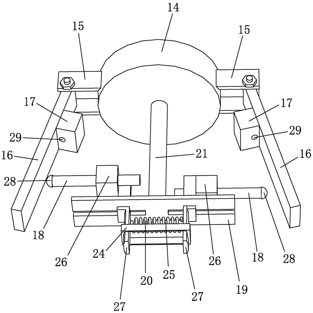
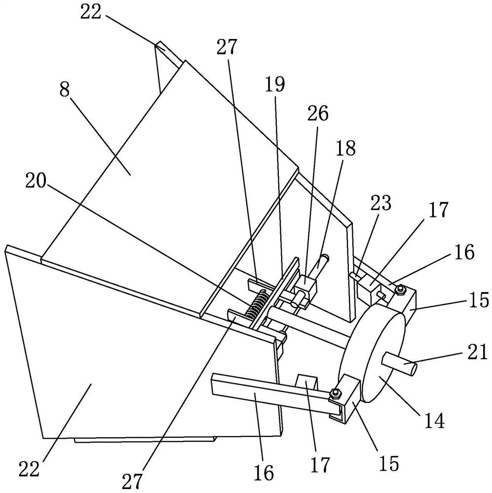
[0057] like Figure 1 to Figure 10 As shown, it is a negative pressure exhaust gas discharge disinfection and sterilizer according to the present invention, which includes a housing 1 and a gas pipeline 2, a junction box 3 is provided on the top of the housing 1, a heating element 4 is arranged in the housing 1, and the heating element 4 Protruding into the housing 1 , the junction box 3 supplies power to the heating element 4 . After the power is turned on, the heating element 4 can be heated to 110°C~200°C, the system differential pressure is ≤2kPa, and the processing air volume is 500m 3 / h, killing efficiency > 99.99%.

[0058] The gas pipeline 2 is mainly an intake pipe and an exhaust pipe, and the intake pipe is connected with the vacuum pump system. If the exhaust port of the exhaust pipe is set in the basement, the exhaust port should be led to the outside; if the exhaust port is set outside or newly led to the outside, the exhaust port should not be at the same heig...


PUM


Abstract

The invention discloses a negative pressure waste gas discharge disinfection and sterilizer and a manufacturing method thereof, which comprises a housing, a gas pipeline, a junction box and a heating element. Both ends of the housing are provided with protective covers, and the size of the opening of the protective cover is along the The center of the shell gradually decreases toward the end, and the inner cavity of the protective cover communicates with the gas pipeline. The method includes: a, installing a protective cover welding device; b, welding to obtain a protective cover with an initial shape; c, welding an inner cavity in the protective cover with an initial shape; d, cutting to obtain a formed protective cover; The sealing plate is welded and fixed; f, the protective cover is painted; g, the protective cover is respectively welded on both ends of the shell; h, the bottom of the junction box is sealed on the shell. The invention can avoid the phenomenon of gas leakage, reduce the temperature of the exhaust at the same time, improve the safety, and increase the processing air volume; and solve the technical problem that the inside of the truss-shaped protective cover is not easy to weld, and increase the vertical pressure bearing of the protective cover Capability, can be welded in batches to get the protective cover.

Description

technical field [0001] The invention belongs to the technical field of thermal inactivation, and in particular relates to a negative pressure exhaust gas discharge sterilizer and a manufacturing method thereof. Background technique [0002] At present, the technology of thermal inactivation is used to continuously dispose of the highly polluted and toxic waste gas discharged from the vacuum suction system of the hospital, and the bacteria, microorganisms, viruses and aerosols that may be entrained in it are inactivated and then discharged cleanly. The technology is widely used in the emission control of poisonous waste gas from the vacuum suction system of major hospitals. [0003] The technology of thermal inactivation has the following advantages: it is a simpler, safer and more effective sterilization and disinfection method, with high killing efficiency, the process only consumes electricity, does not need to add harmful chemicals, does not produce ozone or other regener...

Claims


Application Information

Patent Timeline
Patent Type & Authority Patents(China)
IPC IPC(8): B23P15/00B23K37/04B23K37/00B01D53/00
CPCB01D53/005B01D2257/91B23K37/00B23K37/0426B23P15/00
Inventor 王盛浪杨益韩沈延辉
Owner ZHEJIANG QIANGSHENG MEDICAL ENG
Why Eureka
Try Eureka