
Torque ripple suppression control system and method for flux switching motor

A flux switching motor and torque pulsation technology, applied in the direction of electronically commutated motor control, control system, vector control system, etc., can solve the problem of model predictive control algorithm with many parameters, harmonic injection cannot be accurately compensated, and the effect is not obvious, etc. problems, achieve smooth torque output, good adaptability, and reduce torque ripple

Active Publication Date: 2020-07-17
SOUTHEAST UNIV
View PDF2 Cites 2 Cited by
  • Summary
  • Abstract
  • Description
  • Claims
  • Application Information

AI Technical Summary

Problems solved by technology

The current harmonic injection method based on the positioning torque model and the model predictive control strategy are two typical compensation control strategies, both of which have achieved good control effects, but the former requires finite element analysis of the positioning torque of the motor. In the actual motor operating system, The positioning torque may change due to changes in the assembly process and load conditions, and harmonic injection cannot be accurately compensated, making the effect of this scheme not obvious in the experiment
The latter is designed based on the model predictive control algorithm and the compensation torque model. On the one hand, the compensation torque model is also obtained through offline finite element analysis. On the other hand, the model predictive control structure is different from the traditional double closed-loop vector control structure. Design the corresponding controller structure, the model predictive control algorithm has many parameters, and the parameter adjustment is also relatively complicated

Method used


Image

  • Torque ripple suppression control system and method for flux switching motor
  • Torque ripple suppression control system and method for flux switching motor
  • Torque ripple suppression control system and method for flux switching motor

Examples


Embodiment Construction

[0047] Since the FSPM motor has a high air gap magnetic density, and the stator and rotor have a double salient pole structure, its cogging torque is relatively large. Excessive cogging torque will cause torque ripple, mechanical vibration and noise when the motor is running, which reduces the performance and efficiency of the FSPM motor and limits its application. At present, most torque ripple optimization methods choose to redesign the structure of the flux switching motor. This type of method has a good effect on suppressing the torque ripple of the flux switching motor, but the production cost of non-standard motors is high and the production cycle is long. , the average torque may decrease while suppressing the torque ripple, so this type of method has certain limitations. From the perspective of control, using compensation control to compensate the positioning torque can optimize the output characteristics of the motor after the motor is processed, without redesigning t...


PUM


Abstract

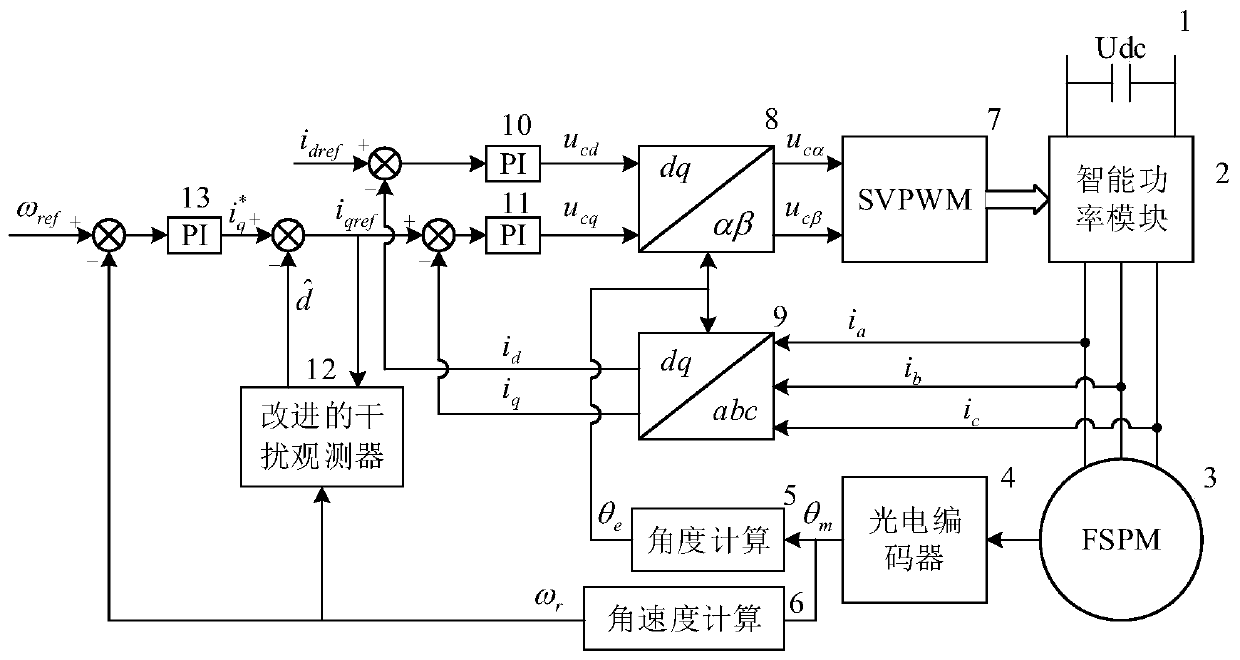
The invention discloses a torque ripple suppression control system and method for a magnetic flux switching motor which is used to control the magnetic flux switching motor. The control method comprises the steps of measuring the rotor position angle theta m of the flux switching motor, and obtaining the rotating speed omega r; according to the rotating speed omega r and a given target rotating speed omega ref, calculating to obtain a component consistent with the cogging torque frequency in the given value observation rotating speed omega r of the q-axis current, obtaining an interference value, and according to the given value interference value of the q-axis current and the actual values of the d-axis current and the q-axis current, calculating to obtain the voltage vector values ucd and ucq; converting the voltage vector values ucd and ucq from dq-alpha beta coordinates to the voltage vectors ucalpha and ucbeta under an alpha-beta coordinate system; and obtaining a three-phase PWMsignal based on the voltage vectors ucalpha and ucbeta, generating a three-phase voltage value according to the three-phase PWM signal, and driving the flux switching motor to operate. According to the technical scheme, only the frequency information of the positioning torque needs to be known, the amplitude phase does not need to be known, and when the amplitude of the positioning torque changes,the compensation value can be corrected in time, and the control effect is guaranteed.

Description

technical field [0001] The invention belongs to the technical field of motor drive, and in particular relates to a torque ripple suppression control system and control method for a magnetic flux switching motor. Background technique [0002] Due to its high power density, small size, and good electromagnetic performance, permanent magnet motors have been widely used in industrial production. At present, the commonly used permanent magnet motors generally place permanent magnets on the rotor, so it is difficult for permanent magnets to dissipate heat. The risk of loss of magnetism is high. In addition, surface-mounted permanent magnet motors also require additional fastening devices to prevent permanent magnets from falling off during high-speed operation, which increases the cost of the motor. [0003] In order to solve the above problems, the researchers proposed a stator permanent magnet motor. Flux-Switching Permanent Magnet (FSPM) is a type of stator permanent magnet bru...

Claims


Application Information

Patent Timeline
Patent Type & Authority Applications(China)
IPC IPC(8): H02P21/05H02P21/22H02P21/13H02P27/12
CPCH02P21/05H02P21/22H02P21/13H02P27/12
Inventor 程明周嘉炜
Owner SOUTHEAST UNIV
Learn More