
Planar capacitor and manufacturing method thereof

A production method and capacitor technology, applied in the field of capacitors, can solve the problems of demanding technical personnel, complicated production process, and low capacitance density, and achieve the effects of reducing the difficulty of production process, diverse and flexible preparation methods, and reducing production costs

Inactive Publication Date: 2020-08-07
深圳市峰泳科技有限公司
View PDF5 Cites 2 Cited by
  • Summary
  • Abstract
  • Description
  • Claims
  • Application Information

AI Technical Summary

Problems solved by technology

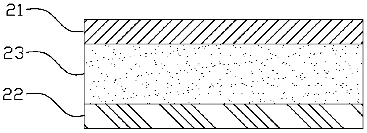
The capacitance density (capacitance per unit area) of existing planar capacitors is generally not high, about 130pF / cm 2 ~10nF / cm 2 , and its production process is complex and difficult, and the thickness of the dielectric layer 23 is generally between 3 and 25um, so the requirements for factory equipment and technical personnel are very strict, and the production cost of the enterprise is high

Method used


Image

  • Planar capacitor and manufacturing method thereof
  • Planar capacitor and manufacturing method thereof
  • Planar capacitor and manufacturing method thereof

Examples


no. 1 example

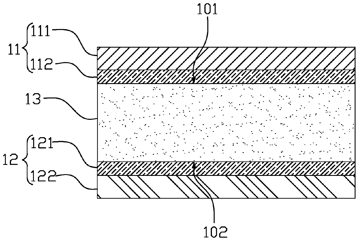
[0028] figure 2 It is a schematic diagram of a partial cross-sectional structure of a planar capacitor of the present invention, such as figure 2 As shown, the planar capacitor includes a first electrode 11, a second electrode 12 and a dielectric layer 13, the dielectric layer 13 is located between the first electrode 11 and the second electrode 12, the dielectric constant of the dielectric layer is greater than 100, and the first electrode 11 includes The first conductive layer 111 and the second conductive layer 112 with viscosity, the first conductive layer 111 is stuck on the second conductive layer 112, the second conductive layer 112 is stuck on the dielectric layer 13, and the second electrode 12 includes the third conductive layer 121 and an adhesive fourth conductive layer 122 , the third conductive layer 121 is adhered to the fourth conductive layer 122 , and the fourth conductive layer 122 is adhered to the dielectric layer 13 . Preferably, the dielectric layer 1...

no. 2 example

[0041] The present invention also relates to a method for manufacturing a planar capacitor, the method comprising:

[0042] Making the first electrode 11, the second electrode 12 and the dielectric layer 13, the dielectric constant of the dielectric layer 13 is greater than 100;

[0043]Wherein, the dielectric layer 13 is located between the first electrode 11 and the second electrode 12, the first electrode 11 includes a first conductive layer 111 and a viscous second conductive layer 112, the first conductive layer 111 sticks to the second conductive layer 112 On, the second conductive layer 112 sticks on the medium layer 13, the second electrode 12 includes the third conductive layer 121 and the fourth conductive layer 122 with viscosity, the third conductive layer 121 sticks on the fourth conductive layer 122, the fourth The conductive layer 122 is glued on the dielectric layer 13 . Preferably, the dielectric layer 13 is made of a mixed dielectric material with a high die...


PUM

PropertyMeasurementUnit
Thicknessaaaaaaaaaa

Abstract

The invention provides planar capacitor which comprises a first electrode, a second electrode and a dielectric layer. The dielectric layer is positioned between the first electrode and the second electrode; the dielectric constant of the dielectric layer is greater than 100, the first electrode comprises a first conducting layer and a second conducting layer with viscosity, the first conducting layer adheres to the second conducting layer, the second conducting layer adheres to the dielectric layer, the second electrode comprises a third conducting layer and a fourth conducting layer with viscosity, the third conducting layer adheres to the fourth conducting layer, and the fourth conducting layer adheres to the dielectric layer. The dielectric layer of the planar capacitor has a relativelyhigh dielectric constant, so that the difficulty of a production process can be greatly reduced, and the production cost is reduced. The invention further relates to a manufacturing method of the planar capacitor.

Description

technical field [0001] The invention relates to the technical field of capacitors, in particular to a planar capacitor and a manufacturing method thereof. Background technique [0002] The current planar capacitor is based on the polymer material system mixed and dispersed with barium titanate particles and epoxy resin, and then formulated with copper foil (that is, serving as the electrodes at both ends of the planar capacitor) and other auxiliary materials (such as dispersant, curing agent) The planar capacitance, and the polymer material must not only ensure that its dielectric constant is high but also ensure the adhesion between the polymer material and the polymer material, between the polymer material and the copper foil, so as to prevent the planar capacitance from falling off during the application , Poor delamination; where barium titanate is a strong dielectric compound material, epoxy resin refers to the general term for a class of polymers containing more than t...

Claims


Application Information

Patent Timeline
IPC IPC(8): H01G4/08H01G4/005H01G4/008
CPCH01G4/005H01G4/008H01G4/08
Inventor 李峰卢星华陶玉红周智勇杨柳
Owner 深圳市峰泳科技有限公司
Learn More