Oil sludge treatment device and system

A kind of technology of sludge and inner casing, which is applied in the direction of pyrolysis sludge, sludge treatment, water/sludge/sewage treatment, etc., can solve the problem that sludge is not easy to decompose and decompose, energy consumption and other problems, and achieves the solution of difficult Effects of treatment, meeting environmental protection requirements, and safe treatment

Pending Publication Date: 2020-08-18
上海浦源科技有限公司
View PDF0 Cites 1 Cited by
  • Summary
  • Abstract
  • Description
  • Claims
  • Application Information

AI Technical Summary

Problems solved by technology

[0005] In view of the problems that the above-mentioned existing sludge treatment devices and systems have the problem that the sludge is not easy to decompose and the decomposition process consumes more energy, the present invention is proposed

Method used


Image

  • Oil sludge treatment device and system
  • Oil sludge treatment device and system
  • Oil sludge treatment device and system

Examples


Embodiment 1

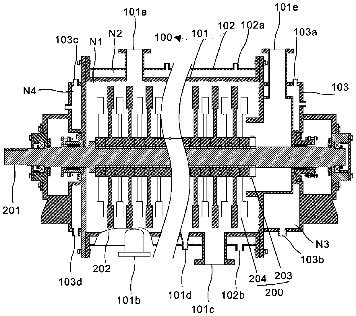
[0041] refer to figure 1 , providing a schematic diagram of the overall structure of a sewage sludge treatment device and system, such as figure 1 , a device and system for treating sewage sludge includes a bearing assembly 100, including an inner casing 101, an outer casing 102 disposed on the periphery of the inner casing 101, and spacers 103 located on both sides of the inner casing 101; and, a hammer mill assembly 200 , comprising a rotating shaft 201 and a first rotor member 202 and a second rotor member 204 arranged alternately on the rotating shaft 201 through locking members 203, the first rotor member 202 and the second rotor member 204 are both in the reaction chamber of the housing 101 within N1.

[0042]Specifically, the main structure of the present invention includes a bearing assembly 100 and a hammer mill assembly 200. Through the mutual cooperation between the bearing assembly 100 and the hammer mill assembly 200, the sludge can be fully mixed, sheared and he...

Embodiment 2

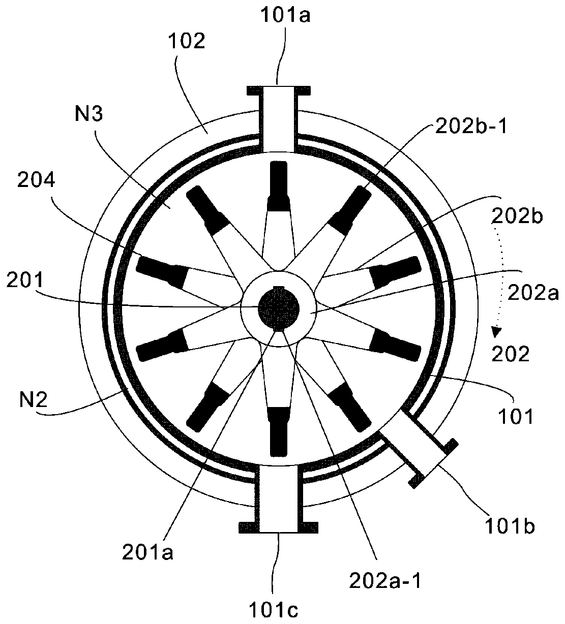
[0048] refer to figure 2 , this embodiment is different from the first embodiment in that: the first rotor parts 202 and the second rotor parts 204 have the same structure and are staggered on the rotating shaft 201, and the staggered first rotor parts 202 and the second rotor parts 204 It is conducive to uniform hammer grinding and can improve the decomposition efficiency. Specifically, the first rotor part 202 and the second rotor part 204 have the same structure and are arranged alternately on the rotating shaft 201. It should be emphasized that not only two sets of rotor parts are installed on the rotating shaft 201, but also several The rotor groups are arranged side by side, and the adjacent rotor parts are staggered at a certain angle. According to the required amount of sludge treatment, 12 to 36 groups of rotor parts are arranged axially along the rotating shaft 201. Preferably, several groups of rotor parts adopt double The method of flat key connection (or spline ...

Embodiment 3

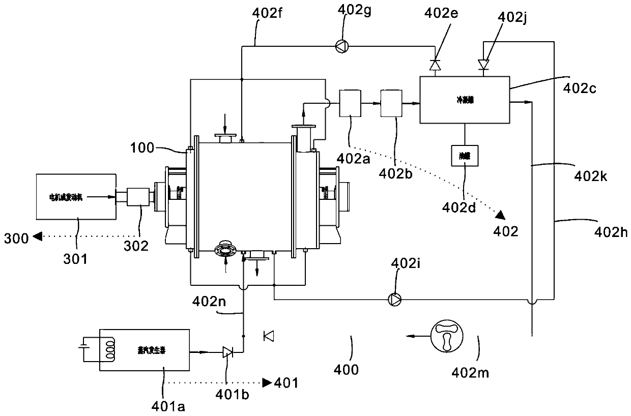
[0053] refer to image 3 , this embodiment is different from the above embodiments in that: this embodiment is a sludge treatment system, which includes a bearing assembly 100, a hammer mill assembly 200, a driving assembly 300, and a heating assembly 400, and the set bearing assembly 100, hammer The mutual cooperation between the grinding assembly 200, the driving assembly 300 and the heating assembly 400 enables the injection of steam, which greatly reduces the evaporation temperature of the oil, improves the processing efficiency, and solves the problem that the fine hammer mill dust is difficult to handle. The reduction has improved the service life of the mechanical structure, enhanced the stability of operation, and can handle oily sludge in a more green, energy-saving, efficient, stable and safe manner, meeting the environmental protection requirements of future development. Specifically, a decomposition reaction chamber and a heating decomposition chamber of sludge are...


PUM

PropertyMeasurementUnit
boiling pointaaaaaaaaaa

Abstract

The invention discloses an oil sludge treatment device, which comprises: a bearing assembly that includes an inner shell, an outer shell arranged at the periphery of the inner shell, and spacing bodies located at the two sides of the inner shell; the hammer grinding assembly that comprises a rotating shaft, a first rotor piece and a second rotor piece, wherein the first rotor piece and the secondrotor piece are arranged on the rotating shaft in a staggered mode through a locking piece, and the first rotor piece and the second rotor piece are both arranged in the reaction cavity of the inner shell; a first heating separation cavity is formed between the inner shell and the outer shell; according to the invention, the rotor pieces and a plurality of heating cavities are arranged, so the oily sludge can be fully heated and hammer-milled; therefore, the oily sludge can be fully decomposed; meanwhile, a thermal desorption mode of combined action of steam heating and hammer milling is adopted, the evaporation temperature of oil is greatly reduced by injecting steam, the treatment efficiency is improved, and the problem that fine hammer milling dust is difficult to treat is solved; the process temperature is reduced, the service life of a mechanical structure is prolonged, and the operation stability is enhanced.

Description

technical field [0001] The invention relates to the technical field of waste oil treatment, in particular to a device and system for treating waste oil sludge. Background technique [0002] Sludge contains oil, water, sediment and other impurities. Other impurities may include drilling waste sludge and oil-contaminated soil, fuller's earth, oil tank sludge, oil shale and fish waste. The composition of the sludge is complex. Direct discharge will cause waste of effective oil, and will cause serious pollution and damage to the ecological environment. Therefore, it is necessary to effectively treat sludge; at present, many sludge treatment processes have been implemented at home and abroad, with continuous pyrolysis process and The industrial production method converts sludge into products such as oil, combustible gas, and solid products that are easy to store, transport, and have high energy density and are convenient to use; however, these processes are likely to cause the se...

Claims


Application Information

Patent Timeline
Patent Type & Authority Applications(China)
IPC IPC(8): C02F11/13C02F11/10C02F11/00
CPCC02F11/00C02F11/10C02F11/13
Inventor 吴雨薇
Owner 上海浦源科技有限公司
Why Eureka
Try Eureka