Large liquid oxygen subcooling degree acquisition system utilizing cooling capacity of liquid hydrogen
A technology for obtaining system and subcooling degree, applied in household refrigeration devices, applications, household appliances, etc., can solve the problems of low refrigeration efficiency, difficult evacuation, polluted liquid oxygen, etc., to achieve large subcooling degree, no safety hazards, The effect of avoiding pollution
- Summary
- Abstract
- Description
- Claims
- Application Information
AI Technical Summary
Problems solved by technology
Method used
Image
Examples
Embodiment 1
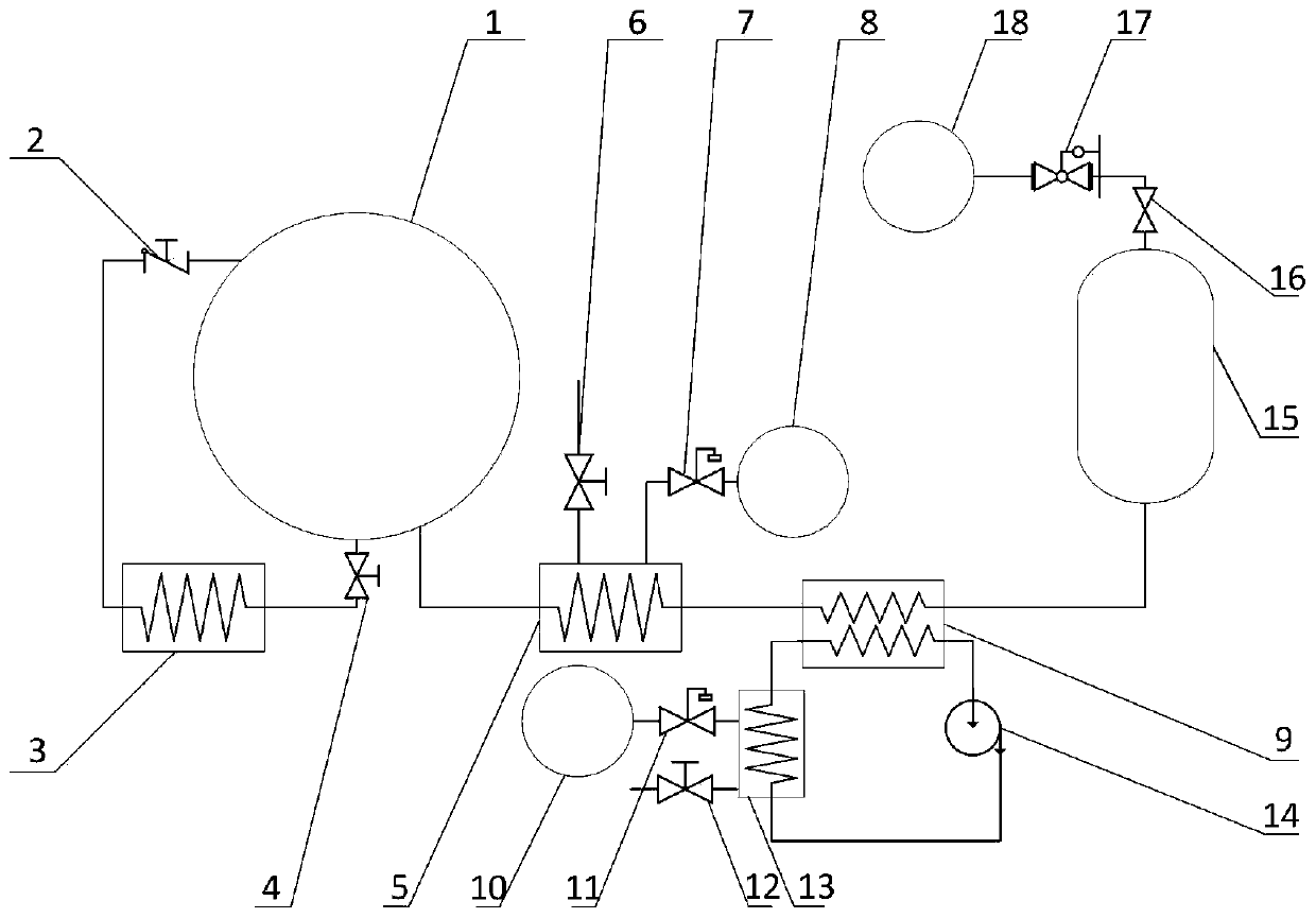
[0039] Example 1, such as figure 1 As shown, a liquid oxygen large subcooling degree acquisition system utilizing the cooling capacity of liquid hydrogen includes a liquid oxygen storage tank 1, the pressurized outlet at the bottom of the liquid oxygen storage tank 1 is connected to the inlet of the first discharge valve 4, and the first discharge The outlet of the valve 4 is connected to the inlet of the air-bath carburetor 3, the outlet of the air-bath carburetor 3 is connected to the inlet of the first return check valve 2, and the outlet of the first return check valve 2 is connected to the return port on the top of the liquid oxygen storage tank 1;
[0040] The discharge port at the bottom of the liquid oxygen storage tank 1 is connected to the liquid oxygen side inlet of the liquid nitrogen bath heat exchanger 5, and the liquid oxygen side outlet of the liquid nitrogen bath heat exchanger 5 is connected to the liquid oxygen side inlet of the oxygen-helium heat exchanger 9...
Embodiment 2
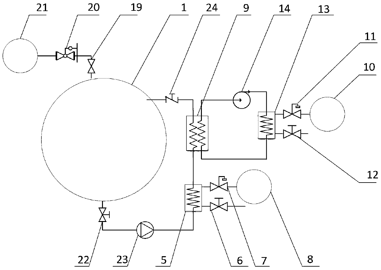
[0050] Embodiment 2, with reference to figure 2 , a system for obtaining large subcooling degree of liquid oxygen using the cooling capacity of liquid hydrogen, adopting the ground circulation supercooling method to prepare deep supercooled liquid oxygen, including a liquid oxygen storage tank 1, the top booster port of the liquid oxygen storage tank 1 passes through the first The second pressure stabilizing valve 19 and the second pressure relief valve 20 are connected to the outlet of the second high-pressure helium cylinder 21; the bottom outlet of the liquid oxygen storage tank 1 is connected to the inlet of the second relief valve 22, and the outlet of the second relief valve 22 is connected to the circulating pump 23 inlet, the outlet of circulation pump 23 is connected to the liquid oxygen side inlet of liquid nitrogen bath heat exchanger 5, and the liquid oxygen side outlet of liquid nitrogen bath heat exchanger 5 is connected to the liquid oxygen side inlet of oxygen-...
Embodiment 3
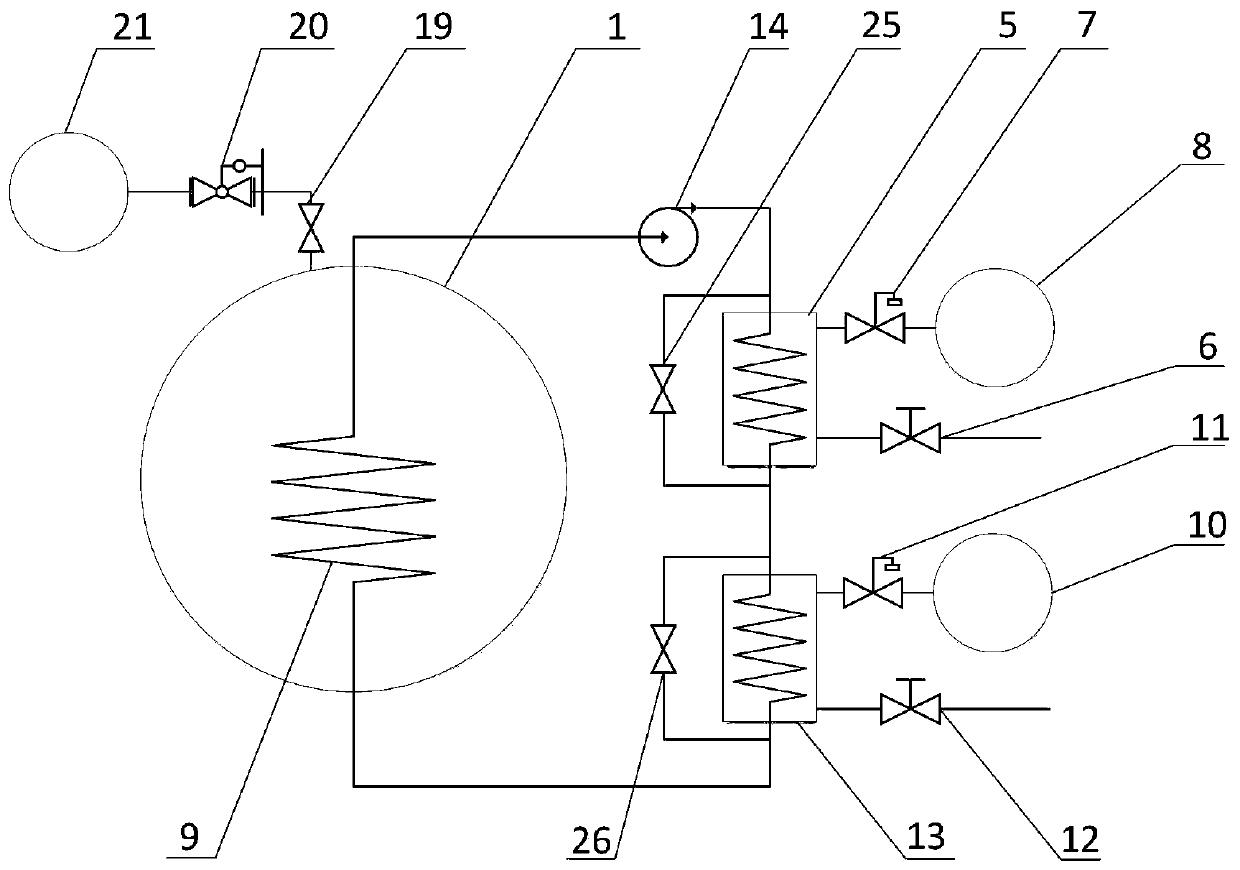
[0054] Example 3, such as image 3 As shown, on the basis of Example 2, the oxygen-helium heat exchanger 9 is placed inside the liquid oxygen storage tank 1, and the outlet of the oxygen-helium heat exchanger 9 extends out of the liquid oxygen storage tank 1 and connects with the inlet of the helium blower 14 , the outlet of the helium blower 14 is connected to the helium side inlet of the liquid nitrogen bath heat exchanger 5, the helium side outlet of the liquid nitrogen bath heat exchanger 5 is connected to the helium side inlet of the helium-hydrogen heat exchanger 13, and the helium - The helium side outlet of the hydrogen heat exchanger 13 is connected to the inlet pipe of the oxygen-helium heat exchanger 9 protruding from the liquid oxygen storage tank 1 .
[0055] A bypass pipe is provided on the helium side of the liquid nitrogen bath heat exchanger 5 to connect to the first bypass valve 25, and the inlet of the first bypass valve 25 is connected to the helium side in...
PUM
 Abstract
Description
Claims
Application Information
 - R&D
- Intellectual Property
- Life Sciences
- Materials
- Tech Scout
- Unparalleled Data Quality
- Higher Quality Content
- 60% Fewer Hallucinations
Browse by: Latest US Patents, China's latest patents, Technical Efficacy Thesaurus, Application Domain, Technology Topic, Popular Technical Reports.
© 2025 PatSnap. All rights reserved.Legal|Privacy policy|Modern Slavery Act Transparency Statement|Sitemap|About US| Contact US: help@patsnap.com


