Rectangular optical frequency comb generation system based on on-chip silicon nitride micro-ring

A technology of silicon nitride microrings and optical frequency combs, applied in optics, nonlinear optics, instruments, etc., can solve the problems of comb tooth bandwidth limitation, increase difficulty, increase device cost complexity, etc., and reduce the pressure of subsequent processing , improve energy conversion efficiency, and solve the effect of edge power reduction

Inactive Publication Date: 2020-09-01
SOUTHWEST UNIV
View PDF6 Cites 2 Cited by
  • Summary
  • Abstract
  • Description
  • Claims
  • Application Information

AI Technical Summary

Problems solved by technology

First of all, in the classic microresonator using the microcavity optical frequency comb generated by dissipative optical solitons, the power of the comb teeth at both ends is significantly reduced (such as image 3 spectrogram), resulting in a large power gap between the two ends and the middle of the comb, and the uneven distribution, which may lead to serious power imbalance and comb bandwidth limitations in the subsequent application of optical frequency combs.
In addition, in order to generate an optical frequency comb of dissipative optical solitons in a microresonator microcavity, it is necessary to rely on the nonlinear effect of the microcavity excited by anomalous GVD and strong laser, and the anomalous GVD puts forward a lot of challenges to the fabrication process of the microcavity. High requirements require special design of the device, which also increases the cost and complexity of the device
Third, the energy conversion efficiency of the microcavity optical frequency comb is not high, usually between a few thousandths and a few percent, which also affects the power level of each optical frequency comb, which means that in the subsequent In optical frequency comb applications, such as optical frequency comb communication, more follow-up processing is required, which increases the difficulty in application

Method used


Image

  • Rectangular optical frequency comb generation system based on on-chip silicon nitride micro-ring
  • Rectangular optical frequency comb generation system based on on-chip silicon nitride micro-ring
  • Rectangular optical frequency comb generation system based on on-chip silicon nitride micro-ring

Examples


Embodiment 1

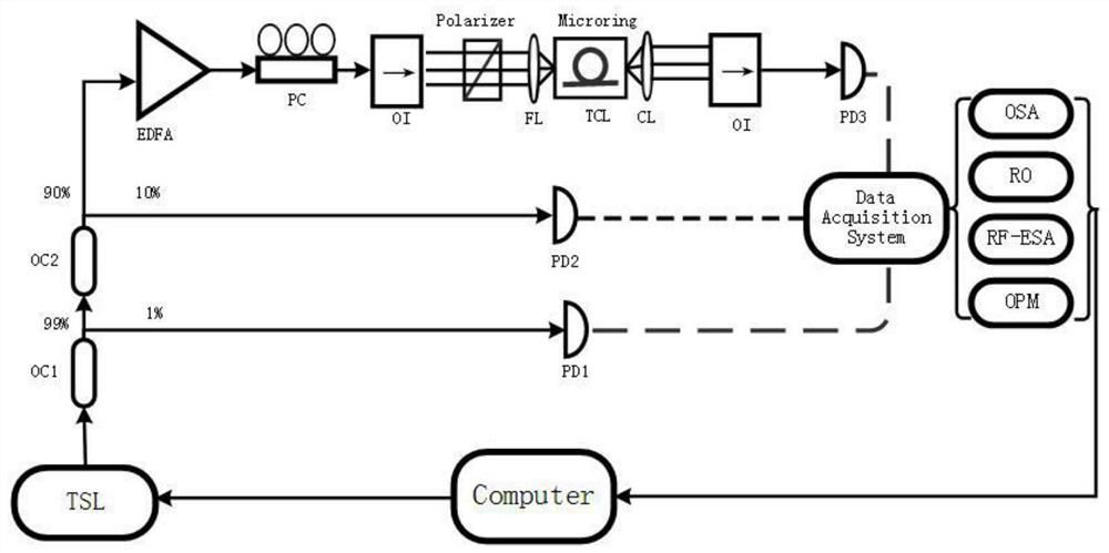
[0058] First, the laser light emitted from the tunable laser (TLS, 1591nm) passes through two optical couplers (OC1 and OC2), and then amplified by the erbium-doped fiber amplifier (EDFA), and the propagation direction is controlled by the polarization controller (PC). The optical isolator (OI) prevents the backward transmission light in the optical path from affecting the light source, and finally enters the Si through the polarizer 3 N 4 Microring resonator (200 microns in diameter). After a series of operations such as amplification and polarization control, the intense laser enters Si with a high quality factor (Q=1500000) and a temperature of 328.15K 3 N 4 When the microring resonator is used, the optical nonlinear effect is generated in the microcavity. When the optical nonlinear effect and the normal group velocity dispersion (89ps 2 / km) reached equilibrium, a femtosecond mode-locked pulse, the time-dissipative soliton, was generated in the microcavity. Finally, th...


PUM

PropertyMeasurementUnit
diameteraaaaaaaaaa

Abstract

The invention provides a rectangular optical frequency comb generation system based on an on-chip silicon nitride micro-ring. The system comprises a tunable laser, a first optical coupler, a second optical coupler, an erbium-doped fiber amplifier, a polarization controller, a first optical isolator, a second optical isolator, a Si3N4 micro-ring resonant cavity, a first photoelectric detector, a second photoelectric detector, a third photoelectric detector, a data acquisition unit and a polarizer. Compared with an optical frequency comb based on dissipative optical solitons in a microcavity inthe prior art, the provided system has the following advantages: the comb tooth power of the rectangular optical frequency comb is remarkably more uniform, and particularly, a problem that the edge power of the optical frequency comb is reduced is solved, so that more comb tooth power is maintained at a high level, and the energy conversion efficiency of the optical frequency comb and the absoluteenergy of the comb teeth are remarkably improved.

Description

technical field [0001] The invention relates to the field of optoelectronics, in particular to a rectangular optical frequency comb generation system based on an on-chip silicon nitride microring. Background technique [0002] Optical Frequency Comb (OFC) refers to the spectrum composed of some discrete, evenly spaced frequency components on the spectrum. Optical frequency combs not only have the time-domain characteristics of ultrashort pulses, which are characterized by ultrashort laser pulse sequences with equal time intervals; they also have the frequency-domain characteristics of narrow-linewidth lasers, which represent millions of discrete narrow-linewidths A collection of rate teeth is equivalent to many phase-locked narrow linewidth continuous lasers. The appearance of the optical frequency comb has greatly improved the timing accuracy, and the optical frequency comb has also become a bridge between the optical frequency and the microwave frequency, so that the opti...

Claims


Application Information

Patent Timeline
Patent Type & Authority Applications(China)
IPC IPC(8): G02F1/35
CPCG02F1/3513G02F1/353
Inventor 吴加贵石炳磊彭璐王子健
Owner SOUTHWEST UNIV
Why Eureka
Try Eureka