
Narrow gap thick plate wire filling welding method based on laser scanning

A technology of laser scanning and welding methods, applied in laser welding equipment, welding equipment, metal processing equipment, etc., can solve problems such as unfused, unfused sidewall interlayers, etc., to achieve increased area, sufficient heat input, and reduced layers The effect of poor fusion

Active Publication Date: 2020-09-04
XI AN JIAOTONG UNIV
View PDF8 Cites 3 Cited by
  • Summary
  • Abstract
  • Description
  • Claims
  • Application Information

AI Technical Summary

Problems solved by technology

[0009] Aiming at the problems existing in the prior art, the present invention proposes a narrow-gap thick-plate wire-fill welding method based on laser scanning. The present invention aims at narrow-gap laser wire-fill welding of thick plates, and overcomes the problem of sidewall welding in the thick-plate laser wire-fill welding process. Emergence of lack of fusion and interlayer lack of fusion

Method used


Image

  • Narrow gap thick plate wire filling welding method based on laser scanning
  • Narrow gap thick plate wire filling welding method based on laser scanning
  • Narrow gap thick plate wire filling welding method based on laser scanning

Examples


Embodiment A

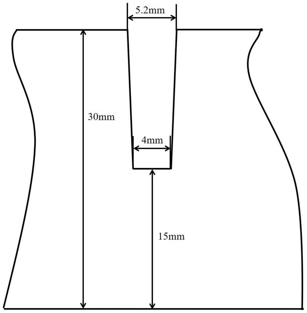
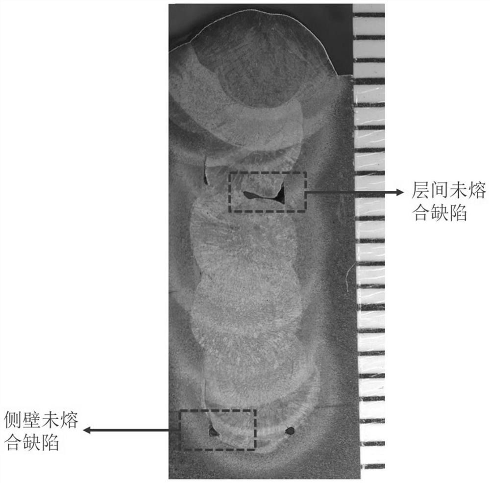
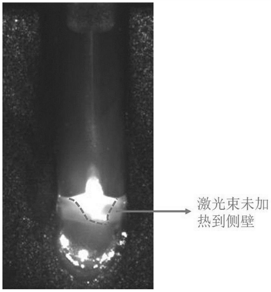
[0055] In this embodiment, the laser does not scan the narrow gap filler wire to weld the Q235 test plate, and the groove form of the test plate is as follows figure 1 As shown, specifically, the Q235 test plate is first polished with sandpaper to remove oxides and impurities on the surface of the Q235 test plate to reveal the metallic luster, and then use acetone to scrub the Q235 test plate; Argon gas with a purity of 99.99% is introduced into the welding gas protection device, and the gas flow rate is 25L / min; adjust the laser welding head so that the angle between the axis of the laser beam emitted by the laser welding head and the vertical direction is 5°; Wire nozzle, so that the angle between the wire feeding nozzle and the plane of the test plate is 45°; turn on the laser, adjust the distance between the light wires to 0mm, and perform single-channel single-layer wire-filled welding along the welding direction, the laser power is 4000W, and the defocus is + 45mm, the w...

Embodiment B

[0057] In this embodiment, the laser scanning narrow gap filler wire welds the Q235 test plate, and the groove form of the test plate is as follows figure 1 As shown, specifically, the Q235 test plate is first polished with sandpaper to remove oxides and impurities on the surface of the Q235 test plate to reveal the metallic luster, and then use acetone to scrub the Q235 test plate; Argon gas with a purity of 99.99% is introduced into the welding gas protection device, and the gas flow rate is 25L / min; adjust the laser swing welding head so that the angle between the axis of the laser beam emitted by the laser swing welding head and the vertical direction is 5°; at the same time Adjust the wire feeding nozzle so that the angle between the wire feeding nozzle and the plane of the test plate is 45°; turn on the laser and scan the laser beam emitted by the laser scanning welding head to perform five-level scanning pre-scanning on the groove area of ​​the low carbon steel test plat...


PUM


Abstract

The invention discloses a narrow gap thick plate wire filling welding method based on laser scanning. The method comprises the following steps: forming a groove on a narrow gap thick plate and executing preprocessing to remove an oxide skin of a to-be-welded area surface; clamping and placing the narrow gap thick plate to inert gas atmosphere by a clamp, adjusting a laser scanning welding head torealize that an axis of a laser beam emitted by the laser scanning welding head and a vertical direction form a first included angle, and meanwhile, adjusting a wire feeding nozzle for wire filling tomake the wire feeding nozzle form a second included angle with a plane of the narrow gap thick plate; scanning and preheating the groove by the laser beam emitted by the laser scanning welding head,wherein scanning efficiency of the laser beam is 50Hz-100Hz, defocus range is +40-+50mm, and amplitude range of the laser beam is 1.2mm-2.3mm; after preheating, performing single layer single bead welding for the to-be-welded area, cleaning welding bead after single layer welding, and immediately repeating the single layer single bead welding after cleaning until fully filling the groove.

Description

technical field [0001] The invention belongs to the field of welding technology, in particular to a laser scanning-based wire-filling welding method for thick plates with narrow gaps. Background technique [0002] Low-carbon steel, high-strength steel and stainless steel have good processability and good weldability, and are widely used in various fields of national production. Traditional welding methods for thick plates include manual arc welding, tungsten inert gas shielded welding, submerged arc welding, etc. Due to the limitation of the size of the welding torch, the groove of the thick plate welded by traditional arc welding will be relatively large, usually requiring multiple layers. One-pass welding, the welding heat input and deformation are large, and it causes a large consumption of welding materials, and the welding efficiency is low. [0003] Li Liqun of Harbin Institute of Technology and others used C02 lasers to perform laser-assisted hot wire multi-layer fil...

Claims


Application Information

Patent Timeline
Patent Type & Authority Applications(China)
IPC IPC(8): B23K26/21B23K26/211B23K26/082
CPCB23K26/082B23K26/21B23K26/211
Inventor 张林杰张乾乾宁杰龙健吴军张黎旭
Owner XI AN JIAOTONG UNIV
Learn More