Manufacturing method of CuNi90/10 alloy socket welding flange

A manufacturing method and welding flange technology, which is applied in the direction of manufacturing tools, metal processing equipment, metal processing machinery parts, etc., can solve the problems of small deformation of the core of the material, large potential safety hazards in use, poor air tightness of the material, etc., and achieve reduction Machining cutting amount, improving strength and good product performance

Active Publication Date: 2020-09-04
SHAANXI SIRUI ADVANCED MATERIALS CO LTD
View PDF10 Cites 2 Cited by
  • Summary
  • Abstract
  • Description
  • Claims
  • Application Information

AI Technical Summary

Problems solved by technology

[0003] Nowadays, there are two common manufacturing methods for socket welding flanges: 1) casting, which has a small amount of cutting and high material utilization, but has poor mechanical properties, poor air tightness of materials, and great potential safety hazards; 2) free casting Ring forging, in this forging method, the diameter of the flange flange is used as the diameter of the ring, and the overall height is the height of the ring. This method wastes a lot of raw materials, requires a lot of turning processing, and the production cost is relatively high, and the core of the material is deformed. The amount is small, the surface deformation is large, and the performance consistency is poor

Method used


Image

  • Manufacturing method of CuNi90/10 alloy socket welding flange
  • Manufacturing method of CuNi90/10 alloy socket welding flange
  • Manufacturing method of CuNi90/10 alloy socket welding flange

Examples


Embodiment 1

[0037] A method for manufacturing a CuNi90 / 10 alloy socket welding flange, comprising the following steps:

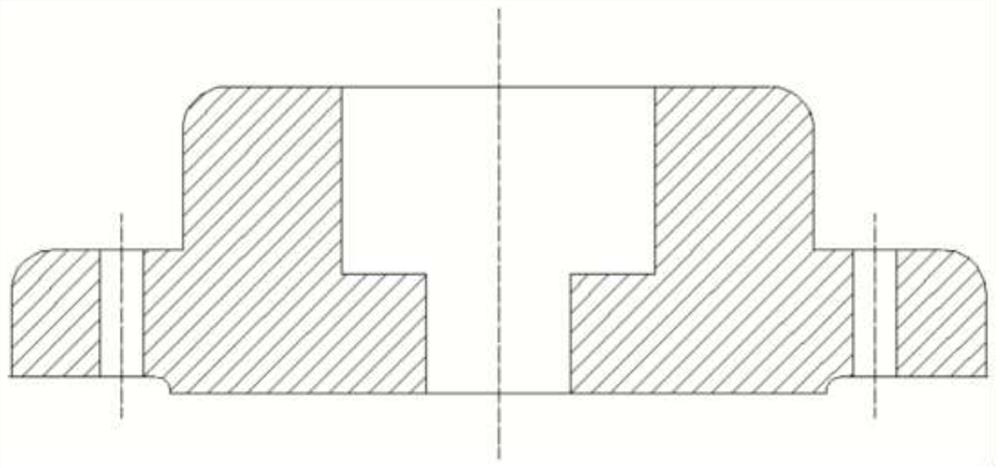
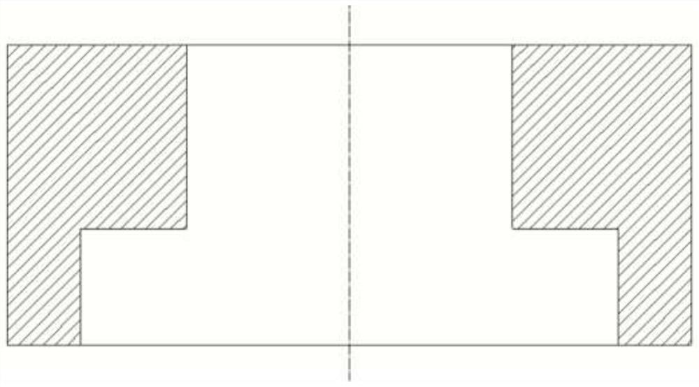
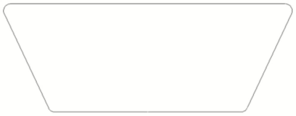
[0038] S1 modeling: such as figure 1 As shown, the shape of the CuNi90 / 10 alloy socket welding flange is a combination of two cylindrical shapes with a small top and a large bottom. There is a through hole in the middle of the CuNi90 / 10 alloy socket welding flange. Dimensions of CuNi90 / 10 alloy socket welding flange, such as Figure 2-4 As shown, a set of mold is manufactured. The mold is made of low carbon steel, which is divided into two parts: the outer mold and the punch, and the punch is divided into two parts: the blind hole punch and the through hole punch;

[0039] S2 Heating Billet: Heating the CuNi90 / 10 alloy ingot to the forging temperature, the ratio of ingot diameter to holding time is 1:1.6, and the numerical units are mm and min respectively, which can accurately control the heating time and ensure the processing quality of subsequent processes , forged...

Embodiment 2

[0047] A method for manufacturing a CuNi90 / 10 alloy socket welding flange, comprising the following steps:

[0048] S1 modeling: such as figure 1 As shown, the shape of the CuNi90 / 10 alloy socket welding flange is a combination of two cylindrical shapes with a small top and a large bottom. There is a through hole in the middle of the CuNi90 / 10 alloy socket welding flange. Dimensions of CuNi90 / 10 alloy socket welding flange, such as Figure 2-4 As shown, a set of mold is manufactured. The mold is made of low carbon steel, which is divided into two parts: the outer mold and the punch, and the punch is divided into two parts: the blind hole punch and the through hole punch;

[0049] S2 heating billet: heating the CuNi90 / 10 alloy ingot to the forging temperature, the ratio of ingot diameter and holding time is 1:1.8, and the numerical units are mm and min respectively, which can accurately control the heating time and ensure the processing quality of the subsequent process , for...

Embodiment 3

[0057] A method for manufacturing a CuNi90 / 10 alloy socket welding flange, comprising the following steps:

[0058] S1 modeling: such as figure 1 As shown, the shape of the CuNi90 / 10 alloy socket welding flange is a combination of two cylindrical shapes with a small top and a large bottom. There is a through hole in the middle of the CuNi90 / 10 alloy socket welding flange. Dimensions of CuNi90 / 10 alloy socket welding flange, such as Figure 2-4 As shown, a set of mold is manufactured. The mold is made of low carbon steel, which is divided into two parts: the outer mold and the punch, and the punch is divided into two parts: the blind hole punch and the through hole punch;

[0059] S2 heating billet: heating the CuNi90 / 10 alloy ingot to the forging temperature, the ratio of ingot diameter to holding time is 1:2.0, and the numerical units are mm and min respectively, which can accurately control the heating time and ensure the processing quality of the subsequent process , forg...


PUM


Abstract

The invention discloses a manufacturing method of a CuNi90/10 alloy socket welding flange. The manufacturing method comprises the following steps that S1, die manufacturing is conducted, specifically,an outer die and a punch are manufactured according to the boundary dimension of the CuNi90/10 alloy socket welding flange; S2, heating and blank making are conducted, specifically, a CuNi90/10 alloyingot is heated to a forging temperature, the temperature is kept for a certain period of time according to the diameter of the ingot, and the ingot is forged on a forging hammer into a blank capableof being put into the outer die; S4, die preheating is conducted, specifically, the die manufactured in the step S1 is preheated in a heating furnace, and the blank manufactured in the step S2 is putinto the outer die for die pressing until a die cavity is filled with CuNi90/10 alloy; S5, punching is conducted, specifically, blind hole punching and through hole punching are sequentially conducted on the die-pressed CuNi90/10 alloy through the punch; and S6, cooling is conducted, specifically, after die forging, the CuNi90/10 alloy material is withdrawn from the die cavity, cooling treatmentis conducted on the CuNi90/10 alloy material, and then the CuNi90/10 alloy socket welding flange is obtained through turning. The manufacturing method is reasonable and effective, and has the advantages of raw material saving, small cutting amount, low production cost, high performance of manufactured products and the like.

Description

technical field [0001] The invention relates to the technical field of design and forging of petroleum pipeline connectors, in particular to a method for manufacturing CuNi90 / 10 alloy socket welding flanges. Background technique [0002] In shipbuilding and oil transportation, pipe connections are required. The commonly used pipe connection method is flange connection. Due to its highly corrosive environment, flanges are required to have high corrosion resistance and wear resistance; In the process, socket welding flanges are required. Cu-Ni-Fe alloy has high corrosion resistance and wear resistance, and is suitable for manufacturing shipbuilding and oil transportation socket welding flanges. [0003] Nowadays, there are two common manufacturing methods of socket welding flanges: 1) casting, which has a small amount of cutting and high material utilization rate, but has poor mechanical properties, poor air tightness of materials, and great potential safety hazards; 2) free ...

Claims


Application Information

Patent Timeline
Patent Type & Authority Applications(China)
IPC IPC(8): B23P15/00B23Q11/10C22C9/06C25D3/12
CPCB23P15/00B23Q11/10C22C9/06C25D3/12
Inventor 吴斌靖林庾高峰李小阳马明月王聪利
Owner SHAANXI SIRUI ADVANCED MATERIALS CO LTD
Why Eureka
Try Eureka