Adsorption and decomposition integrated formaldehyde removal equipment

An all-in-one, formaldehyde-based technology, applied in gas treatment, separation methods, and dispersed particle separation, can solve the problems of unfavorable use, large volume, and high cost of use, and achieve the effects of accelerating absorption speed, increasing contact area, and ensuring dryness

Inactive Publication Date: 2020-09-18
吴建友
View PDF5 Cites 1 Cited by
  • Summary
  • Abstract
  • Description
  • Claims
  • Application Information

AI Technical Summary

Problems solved by technology

[0005] The purpose of the present invention is to solve the shortcomings of the prior art that the electrocatalytic formaldehyde removal equipment is large in size, high in use cost, and unfavorable for use in real life, and proposes an adsorption and decomposition integrated formaldehyde removal equipment

Method used


Image

  • Adsorption and decomposition integrated formaldehyde removal equipment
  • Adsorption and decomposition integrated formaldehyde removal equipment
  • Adsorption and decomposition integrated formaldehyde removal equipment

Examples


Embodiment 1

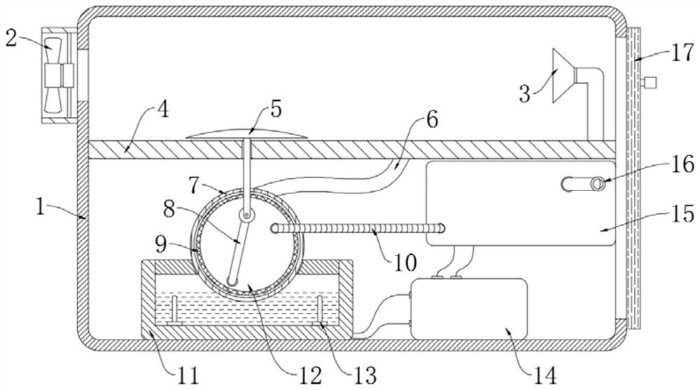
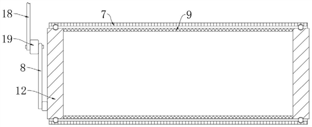
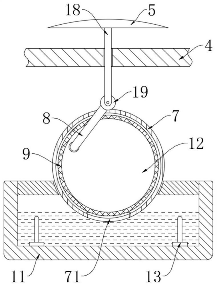
[0025] refer to Figure 1-3 , an adsorption and decomposition integrated formaldehyde removal equipment, including a casing 1, an axial flow fan 2 is installed on the outer wall of the casing 1, and an air inlet corresponding to the position of the axial flow fan 2 is opened on the side wall of the casing 1 The liquid storage box 11 and the control part 14 are fixedly placed on the inner bottom wall of the casing 1. The control part 14 includes structures such as circuit boards, lithium battery packs, and short circuit protection. The liquid storage box 11 contains electrolyte and control parts. 14 two electrodes 13 electrically connected, the electrolyte is sodium sulfate solution or a mixed solution containing sodium sulfite, ammonium sulfate, ammonium chloride and other substances, one of the two electrodes 13 is an inert electrode, such as a graphite rod, and the other electrode 13 is a catalytic electrode rod, such as a carbon fiber rod or a copper electrode rod loaded wi...

Embodiment 2

[0036] refer to Figure 4 , the present embodiment differs from Embodiment 1 in that: a liquid baffle 20 is sealed in the air induction area, and the liquid baffle 20 is located above the air inlet, and a plurality of capillary holes are evenly arranged on the liquid baffle 20, and the baffles A plurality of filter plates 21 are clamped between the liquid plate 20 and the sealing plate 4 .

[0037] When this embodiment is in use, a liquid replenishment port is also provided on the top wall of the casing 1, and water is added to the casing 1 through the liquid replenishment port, so that the upper part of the liquid separator 20 is filled with an aqueous solution. Active downward flow at the hole;

[0038] When the axial flow fan 2 guides the air into the air-inducing area, the high-speed airflow will cause the water to diffuse to the bottom of the liquid separator 20 through the capillary holes, and the water mist will be wrapped around the outside of the dust after mixing wi...


PUM


Abstract

The invention discloses adsorption and decomposition integrated formaldehyde removal equipment. The equipment comprises a machine shell, and an axial flow fan is installed on the outer side wall of the machine shell. An air inlet corresponding to the axial flow fan in position is formed in the side wall of the machine shell. A liquid storage box and a control piece are fixedly placed on the innerbottom wall of the machine shell. Electrolyte and two electrodes electrically connected with the control piece are contained in the liquid storage box. An outer cylinder is embedded in the top wall ofthe liquid storage box, a liquid inlet is formed in the bottom of the outer cylinder, an inner net cylinder is rotationally installed in the outer cylinder in a sealed mode, circular plates are fixedly installed at the two ends of the inner net cylinder in a sealed mode, and a linkage mechanism is arranged on one circular plate. Formaldehyde in air can be uninterruptedly transferred into a film layer, then formaldehyde is transferred into the electrolyte from the film layer to be decomposed, meanwhile, the purposes of adsorbing formaldehyde and decomposing formaldehyde are achieved, energy consumption of equipment is low, the use cost is low, and the purpose of efficiently removing formaldehyde can be achieved on the premise that the specification of an electrolytic tank is not enlarged.

Description

technical field [0001] The invention relates to the technical field of formaldehyde treatment, in particular to an adsorption and decomposition integrated formaldehyde removal equipment. Background technique [0002] At present, the common methods of removing formaldehyde are as follows: ventilation method, photocatalysis method, electrocatalysis method, green plant absorption method, physical adsorption method, among which the effect of green plant absorption method is negligible; physical adsorption method requires frequent replacement of activated carbon At high temperature, the formaldehyde in the activated carbon bag may escape into the air, and the effect of removing aldehyde is not obvious; the ventilation method is effective but takes a long time; the photocatalytic method can only be effective if it is continuously irradiated with ultraviolet lamps. Theoretically efficient aldehyde removal effect, and the electrocatalytic method can be carried out at normal temperat...

Claims


Application Information

Patent Timeline
Patent Type & Authority Applications(China)
IPC IPC(8): B01D53/86B01D53/72B01D50/00
CPCB01D53/8668B01D2258/06B01D50/60
Inventor 吴建友
Owner 吴建友
Why Eureka
Try Eureka