Adaptive optical scanning laser fundus imaging system based on transmission optical element

An adaptive optics and imaging system technology, which is applied in the field of medical imaging diagnosis, can solve the problems of bulky optical aberration and other problems, and achieve the effect of easy optical aberration, improving imaging quality and reducing volume

Pending Publication Date: 2020-09-25
NINGBO UNIV
View PDF1 Cites 2 Cited by
  • Summary
  • Abstract
  • Description
  • Claims
  • Application Information

AI Technical Summary

Problems solved by technology

[0005] The purpose of the present invention is to solve the problem that the existing fundus imaging system uses a reflective system to cause the whole device to be bulky and easily introduce additional optical aberrations, and proposes an adaptive optical scanning laser fundus imaging system based on transmission optical elements

Method used


Image

  • Adaptive optical scanning laser fundus imaging system based on transmission optical element

Examples


specific Embodiment approach 1

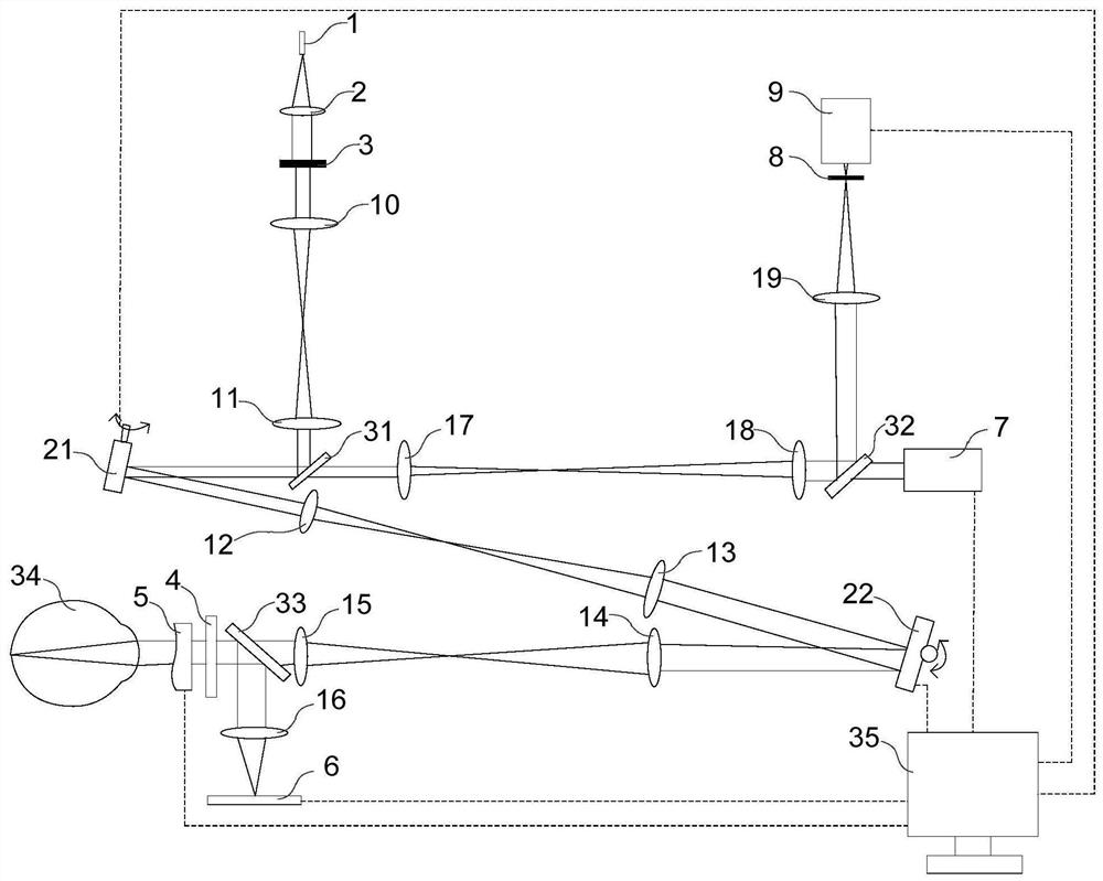
[0015] Specific implementation mode one: combine figure 1 To illustrate this embodiment, an adaptive optics scanning laser fundus imaging system based on transmission optical elements described in this embodiment includes a laser light source 1, a collimating lens 2, a No. 4f optical system, a No. 2 4f optical system, and a No. 3 optical system. 4f optical system, No. 4 4f optical system, diaphragm 3, myopia astigmatism corrector 4, transmission wavefront corrector 5, wavefront sensor 7, first scanning galvanometer 21, second scanning galvanometer 22, first beam splitter Mirror 31, the second beam splitter 32, dichroic mirror 33 and photoelectric detection system;

[0016] After the light emitted by the laser light source 1 is collimated by the collimator lens 2, it passes through the aperture 3 to obtain a parallel beam with a limited diameter, and the aperture 3 is on the focal plane of the collimator lens; after the parallel beam enters the No. 1 4f optical system After th...

specific Embodiment approach 2

[0023] Specific embodiment 2: This embodiment is to further limit the adaptive optics scanning laser fundus imaging system based on transmission optical elements described in specific embodiment 1. In this embodiment, the fundus imaging system also includes an optotype system ;

[0024] The visual target system includes an electronic display screen 6 and a No. 1 lens 16;

[0025] The electronic display screen 6 is used to display the mark, and the light of the mark passes through the No. 1 lens 16, then is reflected by the dichromatic mirror 33, and finally passes through the myopia astigmatism corrector 4 and the transmission wavefront corrector 5 successively, and enters the human eye 34, and imaged on the retina.

[0026] In this embodiment, the purpose of adding an optotype system is to make people focus on the marks displayed on the electronic display screen 6, so as to reduce the shaking of the human eyes.

specific Embodiment approach 3

[0027] Specific Embodiment 3: This embodiment further defines the adaptive optical scanning laser fundus imaging system based on transmission optical elements described in Specific Embodiment 1. In this embodiment, the display signal input terminal of the electronic display screen 6 It is connected with the display signal output end of the computer 35 .

[0028] In this embodiment, the signs displayed on the electronic display screen 6 are controlled by a computer.


PUM


Abstract

The invention discloses an adaptive optical scanning laser fundus imaging system based on a transmission optical element, relates to a medical imaging diagnosis technology for high-resolution imagingof retinas, and aims to solve the problems that a whole device is large in size and extra optical aberration is introduced easily due to adoption of a reflective system in an existing fundus imaging system. A wavefront sensor of the fundus imaging system detects aberration of human eyes and an optical system in real time, the aberration is used as feedback to control a transmission type wavefrontcorrector for real-time correction of the aberration, and retina imaging close to a diffraction limit is realized. The transmission type element is adopted as a main element of the adaptive optical scanning laser fundus imaging system, the size of the system is greatly reduced, and the cost is reduced; and besides, the optical aberration of the transmission type system is easier to control, and the imaging quality of the system can be improved.

Description

technical field [0001] The invention relates to a medical imaging diagnosis technology for high-resolution imaging of the retina. Background technique [0002] The retina is the visual receptor of human beings, and retinal diseases often lead to vision loss or even blindness in patients; the retina is also an extension of the human deep tissue and brain; the eye is the only organ that can directly observe tiny blood vessels and deep tissue under non-invasive conditions in vivo; therefore High-resolution imaging of the retina is an important scientific means to study retina-related diseases, visual mechanisms and brain cognition; however, the real human eye is not a perfect optical system, and the aberration of the eye increases rapidly as the pupil becomes larger. Instead, the resolution of the imaging system will be reduced. Existing optical designs (such as lens compensation) can only correct aberrations such as myopia and astigmatism that we are familiar with, and are po...

Claims


Application Information

Patent Timeline
Patent Type & Authority Applications(China)
IPC IPC(8): A61B3/12A61B3/14A61B3/15A61B3/00G02B27/00
CPCA61B3/0041A61B3/0091A61B3/12A61B3/14A61B3/152G02B27/0025
Inventor 汤珂珂马剑强
Owner NINGBO UNIV
Why Eureka
Try Eureka