
Electric furnace device for component fire protection design and fire protection supervision and using method

A protection design, electric furnace technology, applied in furnace control devices, measuring devices, heat insulation devices, etc., can solve problems such as lack of reliability, increase in cost, and inability to quickly form supervision result reports, so as to reduce heating capacity and control System requirements, the effect of increasing reliability

Pending Publication Date: 2020-10-02
应急管理部天津消防研究所 +1
View PDF15 Cites 5 Cited by
  • Summary
  • Abstract
  • Description
  • Claims
  • Application Information

AI Technical Summary

Problems solved by technology

[0010] (1) The simulation of the real boundary relationship between the protected material and the insulation material is not in place
In terms of fire resistance performance testing of fire retardant coatings, only the surface adhesion between fire retardant coatings (thin and thick types) and the protected material (steel plate) and the heat insulation on the back of the protected material are emphasized, and no clear proposal is made to make the surrounding area of ​​the tested piece A technical solution in which the façade forms an adiabatic boundary, so that the 1D heat transfer problem cannot be accurately simulated
The same is true for the surrounding boundary conditions of the fireproof board, and it is only tested for single-layer boards (single-layer composite boards), and there is no combined protection system composed of "board+board" or "board+cotton" and the protected material The test of the sample naturally cannot take into account the connection and fixation relationship between the multi-layer materials and the thermal resistance between the contact surfaces of each layer.
[0011] (2) The heating curve used meets the standard, but the requirements for the heating capacity and control system of the electric furnace are relatively high, which limits the application of a large number of electric furnaces that manually set the "time-temperature" step-like rising and holding curves, and the technical threshold is high. That is, the corresponding increase in cost
At the same time, when applying the thermal insulation protection structure obtained from the small electric furnace test to the large-size test piece of the standard refractory furnace, it lacks reliability and is often unsafe, that is, the obtained thermal insulation effect cannot meet the design expectations.
[0012] (3) There is not yet a complete set of experimental devices and methods of use that allow relevant companies, research and development units, etc. to carry out "board + board" and "board + cotton (cavity)" tests on the heat insulation effect of protected materials
[0013] (4) There is still a lack of technical solutions for carrying out witness experiments for on-site fire sampling inspections. Although some devices can be used, they are not designed for this purpose, and there are problems such as inconvenient transportation.
Some technologies (application numbers: CN201310610330.8, CN201220055111.9) only focus on intumescent fire retardant coatings or their own physical and chemical performance parameters, but not on protective components or protection systems formed by protected materials and heat insulating materials
On the other hand, although the real-time display of the test data and the wired transmission with the computer were noticed, it was not able to meet the needs of the fire spot inspection site to quickly form a supervision result report for "following the inspection and recording (physical pictures and phenomenon description judgment records)". There is no complete software support

Method used


Image

  • Electric furnace device for component fire protection design and fire protection supervision and using method
  • Electric furnace device for component fire protection design and fire protection supervision and using method
  • Electric furnace device for component fire protection design and fire protection supervision and using method

Examples


Embodiment Construction

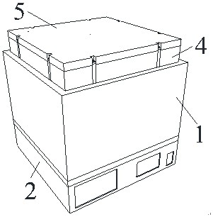
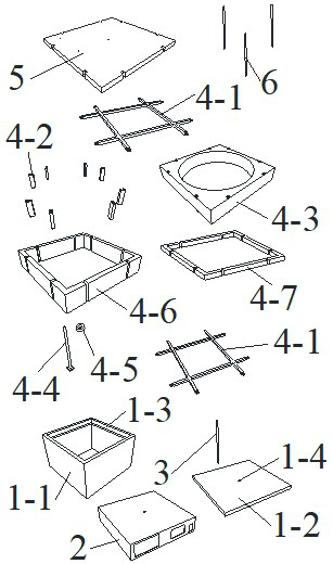
[0126] Such as Figure 1 to Figure 29 As shown, an electric furnace device for component fire protection design and fire supervision, including a furnace body 1 composed of a rectangular hollow furnace wall 1-1 and a square furnace cavity chassis 1-2, the rectangular hollow furnace wall 1-1 is equipped with a heating body To realize the heating in the furnace cavity, it also includes the control display transmission box 2, the furnace cavity thermocouple 3, the constrained heat insulation component 4, the heat insulation cover 5, and the additional thermocouple 6.

[0127] The upper end of the rectangular hollow furnace wall 1-1 is provided with a ring of L-shaped retracted cornices 1-3, and the center of the square furnace cavity chassis 1-2 is provided with a fixing hole 1-4.

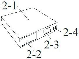
[0128] The control display transmission box 2 is a hollow rectangular box, and a through hole 2-1 is provided in the center of the upper surface of the control display transmission box 2, and a displa...


PUM


Abstract

The invention provides an electric furnace device for component fire protection design and fire protection supervision and a using method. The using method comprises the following steps of: step 1. determining a test scene; step 2. installing the device in position on site; step 3. installing a test sample to be tested, to be specific, step 3A, adopting installation steps described in specifications when a cube test sample is adopted, and step 3B. adopting installation steps described in specifications when a cylindrical test sample is adopted; step 4. unexposed surface heat preservation selection, to be specific, step 4A. when the test sample to be tested is the cube test sample or the cylindrical test sample, adopting installation steps of a heat insulation cover described in specifications, and step 4B. the heat insulation cover is not used; step 5. preparing furnace temperature setting; step 6. selecting a control mode, to be specific, step 6A. using the control test process of a control part, and step 6B, using the control test process of a mobile terminal; and step 7. completing the whole test process, and storing the electric furnace device and the mobile terminal. The electric furnace device can simulate the true boundary relationship between a protected material and a heat insulation material, provides a simple and reliable equivalent heating curve setting method, canquickly form a test report, and greatly improves the efficiency of supervision and law enforcement.

Description

technical field [0001] The invention relates to the fields of fire protection design of building structures, heat insulation performance test of fire protection materials (combined system) and fire protection supervision, and specifically relates to an electric furnace device for fire protection design of components and fire protection supervision and its use method; Combined system) and the real boundary relationship of thermal insulation materials (connecting fixed boundaries, heat transfer boundaries), setting a simple equivalent temperature rise curve, easy to study and try the effect of component fire protection (combined system), and convenient for witnessing during on-site fire spot inspections Component fire protection design for experimentation and rapid formation of supervision result report, electric furnace device and usage method for fire supervision. Background technique [0002] According to the principle of passive fire protection, the current fire protection...

Claims


Application Information

Patent Timeline
IPC IPC(8): F27B17/02F27D1/00F27D1/02F27D19/00B01L7/00B01L7/04G01N25/20G01K13/00
CPCB01L7/00B01L7/04F27B17/02F27D1/0033F27D1/02F27D19/00G01K13/00G01N25/20
Inventor 尹亮阚强李智鸿
Owner 应急管理部天津消防研究所
Learn More