Double perpendicular clamping structure for finely adjusting worm wheel flying cutter in radial direction

A flying knife and worm gear technology, applied in the direction of worm gear, gear teeth, components with teeth, etc., can solve the problems of inconsistent cutting conditions, easy wear of cutting edges, increase auxiliary time, etc., to balance or reduce the peak value of cutting load, tooth The effect of improving shape accuracy and productivity, and improving tooth shape accuracy and productivity

Pending Publication Date: 2020-10-09
中钢集团衡阳机械有限公司
View PDF1 Cites 0 Cited by
  • Summary
  • Abstract
  • Description
  • Claims
  • Application Information

AI Technical Summary

Problems solved by technology

[0002] like figure 1 As shown, the patent No. ZL201620859463.8 discloses a double clamping structure of a worm wheel flying knife (applied for an invention patent at the same time), because the flying knife 7 of the clamping structure protrudes from the radial direction on the tool bar 1 The adjustment of the position (extrusion) is by changing the thickness of the positioning flat washer 3, such as adding a thin gasket or replacing the positioning flat washer 3, so the counterbore bottom plane 22 of the related round through hole and the worm wheel flying knife The accuracy of the positioning plane 71 has certain requirements, so the radial position adjustment accuracy of the flying knife 7 is not high enough, and the adjustment is inconvenient, and it is difficult to achieve precise adjustment. It is difficult to guarantee the radial position of the flying knife 7 protruding from the tool bar 1; To replace the positioning flat washer 3, the entire flying knife 7 has to be taken out of the round through hole 2, which increases the auxiliary time. After the flying knife 7 has been reground many times, the number of positioning flat washers 3 is too large to be easy to manage, and the relative cost is also high ;Due to long-term use or improper storage, the knife rod 1 and the positioning ejector rod 5 are slightly bent or deformed, and the positioning ejector rod 5 is not flexible enough to slide and rotate in the circular light hole 41 of the center hole or even stuck, and the slender positioning ejector rod 5 And the deeper circular light hole 41 has higher precision and is inconvenient to manufacture; while the existing technology can ensure the consistency of the production of the flying knife and the knife holder, and has a high precision, which only meets the requirements for accurate production of the flying knife and the knife holder. The radial position of the knife 7 protruding from the knife bar 1 is one of the conditions for correct use, thus restricting the improvement of the accuracy and productivity of the worm gear
[0003] Since the tightening screw 10 can only produce the force (pull force) facing away from the flying knife head, in order to obtain the double superimposed force boosting and self-locking effect formed by the tightening screw 10 and the inclined wedge (the inclined plane of the positioning ejector rod 5), the flying The opening direction of the acute angle θ between the straight shank of the knife circle and the oblique plane 73 and its axis can only face the flying knife head 74 (the big head of the acute angle θ is in the direction of the flying knife head); while the intermittent cutting force always faces the center of the tool holder 1 , the cutting force changes the gap size and direction of the working tooth flanks of the tension screw 10 thread pairs, and the cutting is unstable, so it is difficult to ensure the roughness of the tooth surface. The direct impact will affect the dynamic stiffness of the cutting tool process system, restricting the improvement of productivity and tooth surface roughness, thus limiting the diversity of the clamping structure and the best positioning and clamping effect, because the number of flying knives is very small and the cutting amount Large, the cutting edge is easy to wear, and the local wear is faster, which increases the cutting resistance, and because the worm wheel of the flying knife is tangentially fed, when the flying knife rolls from the cutting end to the cutting end, the cutting edge of the flying knife moves from the cutting end to the cutting end. Cutting from one side to both sides and then to the other side, the flying knife produces a large periodical alternating stress along its axis, and the cutting conditions of the cutting edges on both sides of the flying knife are inconsistent, so for powerful cutting and high precision worm gear is not up to the task

Method used


Image

  • Double perpendicular clamping structure for finely adjusting worm wheel flying cutter in radial direction
  • Double perpendicular clamping structure for finely adjusting worm wheel flying cutter in radial direction
  • Double perpendicular clamping structure for finely adjusting worm wheel flying cutter in radial direction

Examples


Embodiment approach 1

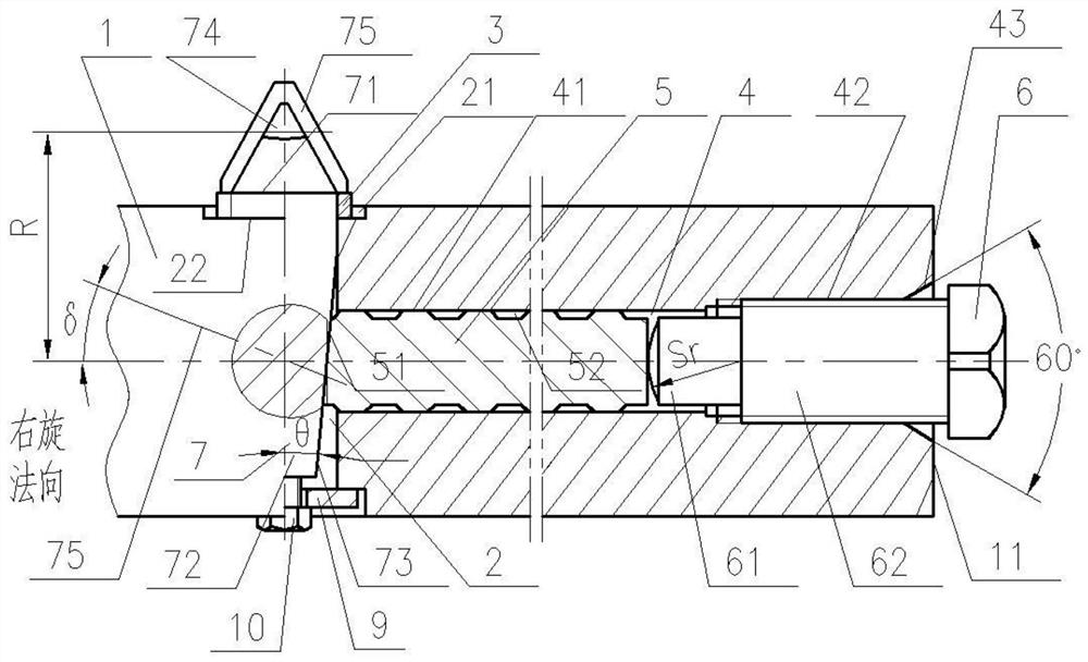
[0068] Such as figure 2 The clamping structure of a worm gear flying knife shown includes a tool bar 1, and the tool bar 1 is composed of an active end with a tapered shank (not shown in the figure) and a slender passive end. The central blind hole 4 facing the active end and concentric with the centerline of rotation of the cutter bar 1 is provided at the end of the tool bar 1. At a proper position in the middle of the tool bar 1, there are installation and clamping and fine-tuning flying knife circles along the radial direction of the center line of the tool bar 1 rotation. The two-stage stepped concentric hole 2 of the straight handle 72, the large hole of the two-stage stepped concentric hole 2 is a cylindrical hole 21, and the small hole is a screw through hole 22, and the locking screw 8 is provided with two sections with the same rotation direction but different pitches. The threads are respectively connected with the concentric screw holes provided on the screw throug...

Embodiment approach 2

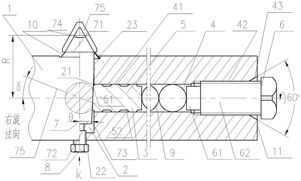
[0117] image 3 Reflecting the specific structure of another embodiment of the present invention, this embodiment is different from Embodiment 1, mainly in that the force applying member 6 is an electro-hydraulic push rod or a hydraulic or pneumatic cylinder and a gas-hydraulic booster mechanism. Positioning and connection with the cutter bar 1; specifically, the larger diameter part of the central blind hole 4 (entry end) is a circular light hole 42, so as to facilitate the sliding positioning of the force applying member 6, and the passive end surface 11 There are several screw holes connected with the force applying member 6, and the hobbed worm wheel is left-handed.

[0118] A further technical solution is: the force-applying member 6 adopts an electro-hydraulic push rod or a hydraulic or pneumatic cylinder and a gas-hydraulic booster mechanism, and the axial force is generated by hydraulic, pneumatic or electric energy. The piston rod serves as a force application termin...

Embodiment approach 3

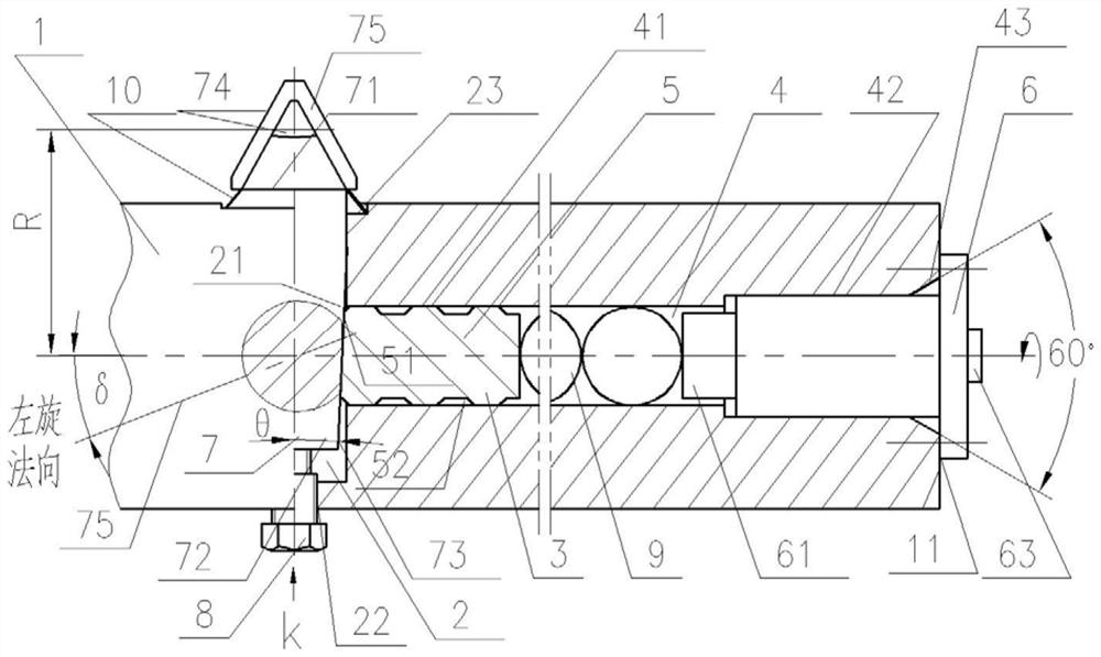
[0122] Figure 4 Reflecting the specific structure of another embodiment of the present invention, this embodiment is different from Example 2 in that the force applying member 6, and δ=0°, specifically, the force applying member 6 adopts a spring or a spring assembly, Figure 6 Shown inside the center blind hole 4 is the Belleville spring and adjusting flat washer.

[0123] A further technical solution is: the force application member 6 adopts a spring or a spring assembly, and the spring deforms uniformly and elastically after being compressed by force, and the elastic force generates an axial force, which pushes the force application terminal 61 to move axially, and is adjusted by adjusting a flat washer or a screw. elastic.

[0124] When the spring is stressed and compressed, it deforms uniformly and elastically, and the force-applying terminal 61 moves axially to generate an axial force. Through several of the balls 9, the inclined end surface 51 at the opposite end of t...


PUM


Abstract

The invention relates to a double perpendicular clamping structure for finely adjusting a worm wheel flying cutter in the radial direction. A center blind hole which faces a driving end and is concentric with the rotary center of a cutter bar is arranged at the driven end of the cutter bar, and a two sections of stepped concentric holes are formed in the radial direction of the rotary center lineof the cutter bar, the large hole is a cylindrical hole, and the small hole is a threaded through hole. Two sections of threads same in turning direction and different in screw pitch are arranged on alocking screw and are connected with the threaded through hole and a screw hole in a round and straight handle of the flying cutter correspondingly. An elastic part is arranged between the plane of the input end of the cylindrical hole and the plane of a cutter bit of the flying cutter, and a positioning and clamping mechanism is arranged in the center blind hole. Under the combined action of thelocking screw and a force applying component, the inclined end face of the opposite end of a positioning ejector rod slides to the cutting plane of the round and straight handle of the flying cutterto form close face contact, the flying cutter is fastened in the cylindrical hole and never loosens after being precisely and finely adjusted and clamped in the radial direction, and the cutting portion of the flying cutter is located at the position the same as a working worm. The technical scheme is suitable for roll cutting a worm wheel small in cutter bar diameter, high in precision and largein cutting force.

Description

technical field [0001] The invention relates to a double vertical clamping structure for radially precise and fine-tuning worm gear flying cutters, which is mainly used for large-lead-angle cylindrical worm drives with small diameters of working worms, high precision and roughness of worm gear tooth surfaces, and large cutting resistance. Worm gear hobbing. Background technique [0002] Such as figure 1 As shown, the patent No. ZL201620859463.8 discloses a double clamping structure of a worm wheel flying knife (applied for an invention patent at the same time), because the flying knife 7 of the clamping structure protrudes from the radial direction on the tool bar 1 The adjustment of the position (extrusion) is by changing the thickness of the positioning flat washer 3, such as adding a thin gasket or replacing the positioning flat washer 3, so the counterbore bottom plane 22 of the related round through hole and the worm wheel flying knife The accuracy of the positioning ...

Claims


Application Information

Patent Timeline
Patent Type & Authority Applications(China)
IPC IPC(8): B23F23/12B23F11/00
CPCB23F11/00B23F23/1243
Inventor 周湘衡
Owner 中钢集团衡阳机械有限公司
Why Eureka
Try Eureka