A zoned tissue combustion self-denitration system and process with a reduction furnace and a decomposition furnace

A technology of partition organization and decomposition furnace, which is applied in the direction of furnace components, furnaces, separation methods, etc., can solve the problems of short residence time of denitrification reaction, limited space of oxygen-poor combustion area, and inability to reduce NOx, etc., so as to reduce the cost of environmental protection treatment of enterprises , strong operability and practicability, and the effect of improving the efficiency of self-denitration

Active Publication Date: 2021-11-02
TIANJIN CEMENT IND DESIGN & RES INST
View PDF5 Cites 0 Cited by
  • Summary
  • Abstract
  • Description
  • Claims
  • Application Information

AI Technical Summary

Problems solved by technology

[0013] (1) In the existing linear calciner, the kiln gas enters directly from the bottom of the calciner. Even if the fuel is graded and burned, a reduction zone is formed at the cone of the calciner, which has a certain effect on reducing NOx in the flue gas from the kiln. However, due to The flue gas from the kiln enters the furnace directly, the space of the oxygen-poor combustion zone is limited, the residence time of the denitrification reaction is short, and the denitrification efficiency is generally about 30%.
[0014] (2) The fuel combustion rate of the existing calciner is limited by the temperature of the combustion zone and cannot be burned quickly. It is necessary to increase the volume of the calciner and prolong the combustion time to meet the demand for combustion. On the one hand, it increases investment and space occupation, and on the other hand Increased equipment surface heat dissipation energy consumption
[0015] (3) The temperature in the combustion zone of the calciner is limited by the crust on the furnace wall, which makes it difficult to further increase the temperature in the combustion zone in the existing technology
When the temperature in the combustion zone is too high, the raw material is prone to liquid phase at high temperature, resulting in skinning problems on the furnace wall
If the combustion temperature of the calciner is too high, it is easy to burn out the refractory material of the furnace wall
[0016] (4) The calciner fuel staged combustion method can only reduce the NOx produced in the rotary kiln, but cannot reduce the NOx produced by the combustion of the fuel itself in the calciner
Moreover, it is relatively difficult to ignite and ignite the fuel in the calciner, which is likely to cause fluctuations in working conditions and affect the stability of the cement production process.
[0017] (5) The method of gradient combustion in the existing calciner is limited to the interior of the calciner
Restricted by factors such as the volume of the calciner and the space of the site, the overall denitrification effect needs to be improved

Method used


Image

  • A zoned tissue combustion self-denitration system and process with a reduction furnace and a decomposition furnace
  • A zoned tissue combustion self-denitration system and process with a reduction furnace and a decomposition furnace
  • A zoned tissue combustion self-denitration system and process with a reduction furnace and a decomposition furnace

Examples


Embodiment 1

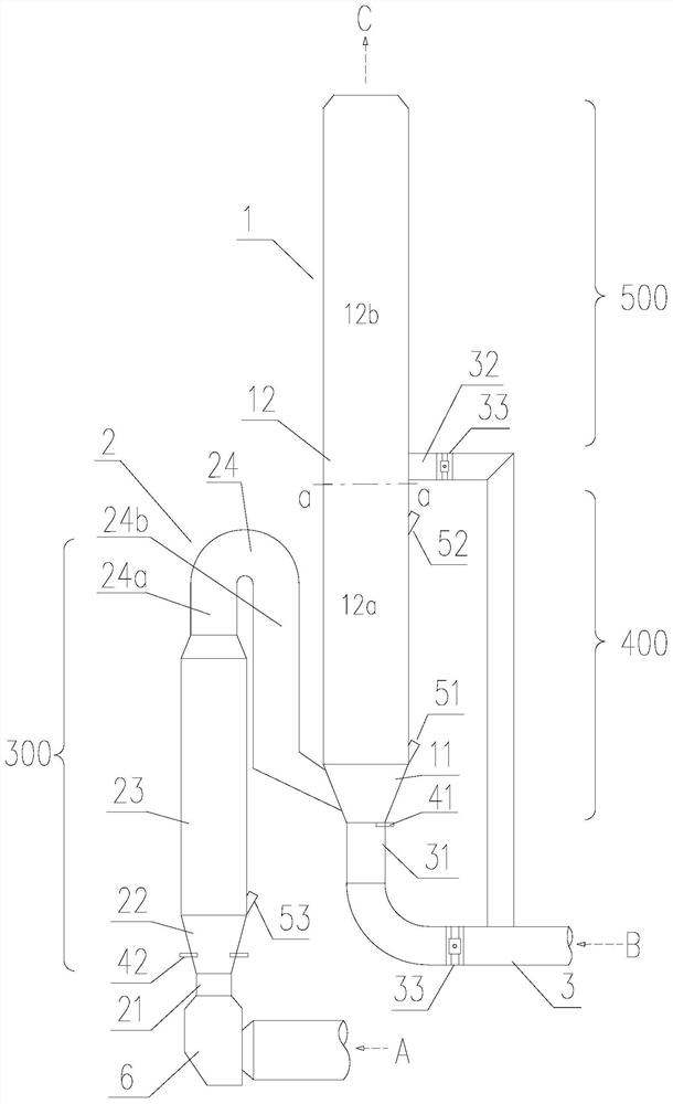
[0077] see Figure 1~4 , the embodiment of the present invention provides a zone organization combustion self-denitration system with a reduction furnace and a decomposition furnace, including a rotary kiln, a kiln tail smoke chamber 6 connected to the kiln tail of the rotary kiln, a decomposition furnace 1, a kiln tail smoke chamber 6 and The reduction furnace 2 of the decomposition furnace 1 and the tertiary air duct 3; The calciner 1, the reduction furnace 2 and the tertiary air duct 3 are all equipped with refractory materials.

[0078] The calciner 1 is located after the reduction furnace 2 , and the flue gas from the reduction furnace 2 and the tertiary air B are combined in the calciner 1 . The calciner 1 is composed of a calciner cone 11 and a calciner column 12 . The outlet of the reduction furnace 2 is connected to the side of the calciner cone 11 or the bottom side of the calciner cylinder 12. In this embodiment, the outlet of the reduction furnace 2 is connected ...

Embodiment 2

[0091] The difference from Embodiment 1 is that the calciner cylinder 12 is provided with a narrowing 13 in the middle of the calciner.

[0092] see Figure 5 , The calciner cylinder 12 is provided with a calciner middle shrinkage 13 . The shrinkage 13 in the middle of the calciner is located below the upper feeding point 52 of the raw meal of the calciner. The raw meal that enters from the raw meal upper feeding point 52 of the calciner tends to move downward under the action of gravity. By setting the calciner middle neck 13 below the raw meal upper feed point 52 of the calciner, the cross section at the neck The wind speed becomes larger than that of the cross-section of the cylinder, which can effectively reduce the falling height of raw materials and prevent material collapse in the calciner.

Embodiment 3

[0094] The difference from Embodiment 1 is that a discharge bin 71 , a material pipe 72 and an air lock valve 73 are arranged below the bottom elbow 311 of the tertiary air lower branch pipe.

[0095] see Image 6 . Preferably, a discharge bin 71 and a material pipe 72 connected to the discharge bin 71 are arranged below the bottom elbow of the lower branch pipe 31 of the tertiary air duct, and both ends of the material pipe 72 are connected to the discharge bin 71 and the kiln tail smoke chamber 6 . When there is an accident shutdown, the materials in the decomposition furnace can fall into the discharge bin 71 under the action of gravity, and enter the kiln tail smoke chamber 6 through the material pipe 72, and enter the rotary kiln, without manual cleaning of materials. The material pipe 72 is provided with an air lock valve 73, which is used to prevent or reduce the exiting kiln flue gas in the kiln tail smoke chamber 6 from blowing into the calciner from the material pip...


PUM


Abstract

The invention discloses a self-denitrification system and process for zoned tissue combustion with a reduction furnace and a decomposition furnace. A reduction furnace is installed between the kiln tail smoke chamber and the decomposition furnace. The bottom of the calciner cone is connected to form a horizontally partitioned combustion environment with a central oxygen-rich zone and a peripheral low-oxygen zone on the calciner cross-section; The space inside the calciner below the upper branch pipe is the weak reduction zone, and the space inside the calciner above the upper branch pipe of the tertiary air is the burnout zone, forming a longitudinal gradient combustion environment combining strong reduction zone-weak reduction zone-burnout zone. The horizontal partition combustion environment is realized by the tertiary air entering vertically upward from the bottom center of the calciner, and the flue gas is realized by the spiral tangential rotating air entering from the side of the calciner; the vertical gradient combustion environment is realized by fuel graded feeding and tertiary air distribution. The present invention realizes self-denitrification through zoned organization combustion as a whole, and improves self-denitrification efficiency.

Description

technical field [0001] The invention relates to the technical field of flue gas denitrification in the cement industry, in particular to a zone-organized combustion self-denitration system and process with a reduction furnace and a decomposition furnace. Background technique [0002] The calciner is the key equipment in the cement production process. The main component of cement raw meal is calcium carbonate, and the carbonate in cement raw meal is decomposed into oxides in the calciner, which provides a basis for the subsequent clinker sintering reaction in the rotary kiln. Since the decomposition of carbonate needs to absorb a large amount of heat, a certain amount of fuel needs to be fed into the decomposition furnace to supply it. Generally speaking, the fuel in the calciner accounts for about 60% of the fuel consumption in the entire cement clinker calcination process. The combustion status of the fuel in the decomposition directly affects the product energy consumpti...

Claims


Application Information

Patent Timeline
Patent Type & Authority Patents(China)
IPC IPC(8): F27B19/04F27D17/00B01D53/76B01D53/56
CPCB01D53/56B01D53/76B01D2258/0283F27B19/04F27D17/008
Inventor 陈昌华彭学平胡芝娟陈廷伟林敏燕
Owner TIANJIN CEMENT IND DESIGN & RES INST
Why Eureka
Try Eureka