
Energy-saving and environment-friendly heat-conducting oil boiler

A heat-conducting oil boiler, energy-saving and environmental protection technology, applied in the field of boilers, can solve problems such as energy waste and low thermal efficiency, and achieve the effects of improving thermal efficiency, increasing heating surface, and increasing the temperature of cold air entering the furnace

Pending Publication Date: 2020-10-13
QINGDAO FERROLI HEATING & VENTILATION & TEMPERATURE CONTROL TECH EQUIP MFG CO LTD
View PDF0 Cites 2 Cited by
  • Summary
  • Abstract
  • Description
  • Claims
  • Application Information

AI Technical Summary

Problems solved by technology

Since the temperature of the medium in the heat-conducting oil boiler is relatively high, usually 260-320°C, the exhaust gas temperature of the boiler is also relatively high, usually above 300°C, resulting in waste of energy and low thermal efficiency.

Method used


Image

  • Energy-saving and environment-friendly heat-conducting oil boiler
  • Energy-saving and environment-friendly heat-conducting oil boiler
  • Energy-saving and environment-friendly heat-conducting oil boiler

Examples


Embodiment 1

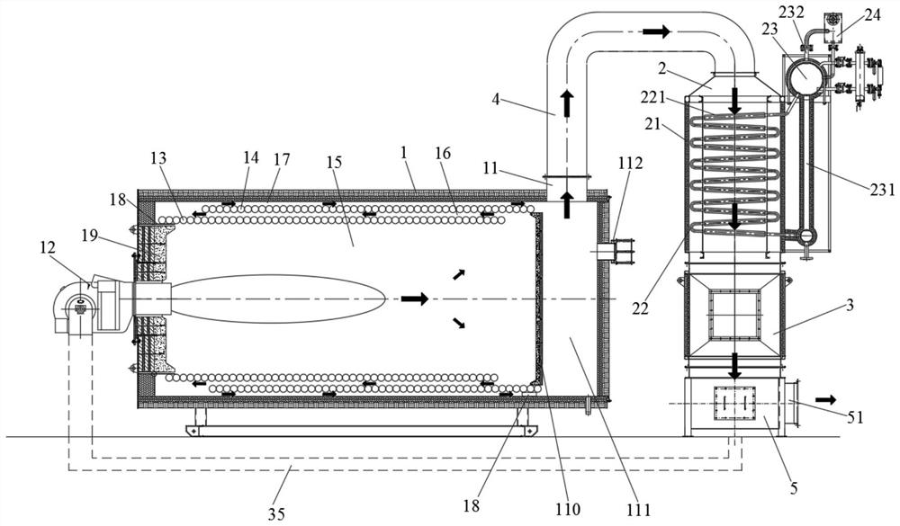
[0042] Such as figure 1 As shown, an energy-saving and environment-friendly heat-conducting oil boiler includes a boiler host 1, a waste heat boiler 2, and an air preheater 3;

[0043] The waste heat boiler 2 includes a vertical body 21; the vertical body 21 is provided with several rows of vertical serpentine heat exchange tubes 22, and the straight pipe sections of the vertical serpentine heat exchange tubes 22 are arranged along the vertical serpentine heat exchange tube. The flow direction of the medium in the heat pipe 22 is inclined upward, and the inclined tube bundle arrangement can make the steam in the steam-water mixture generated in the vertical serpentine heat exchange tube 22 quickly enter the upper steam drum 23, preventing the boiler from running , a large amount of steam accumulates in the vertical serpentine heat exchange tube 22, which affects the safe operation of the boiler; the upper outlet of the vertical serpentine heat exchange tube 22 communicates wit...

Embodiment 2

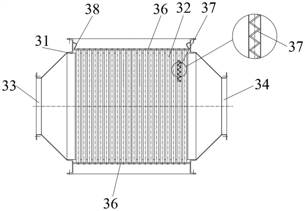
[0056] On the basis of Example 1, such as image 3 As shown, the top and bottom of the air preheater 3 are respectively fixed with horizontal tube sheets 36; the two ends of the vertical heat exchange tubes 32 pass through the corresponding horizontal tube sheets 36 and are fixedly connected with the horizontal tube sheets 36; The lower horizontal tube plate 36 is connected to the external frame 31 , and the upper horizontal tube plate 36 is connected to the external frame 31 through an expansion joint 38 .

[0057] Among them, the top of the vertical heat exchange tube 32 communicates with the flue gas outlet of the waste heat boiler 2, and the bottom of the vertical heat exchange tube 32 communicates with the smoke collection chamber 5; On the other hand, the heat exchange tube 32 also separates the air circulation cavity from the flue gas circulation cavity in the vertical heat exchange tube 32 .

[0058] Preferably, the vertical heat exchange tube 32 is provided with a sp...

Embodiment 3

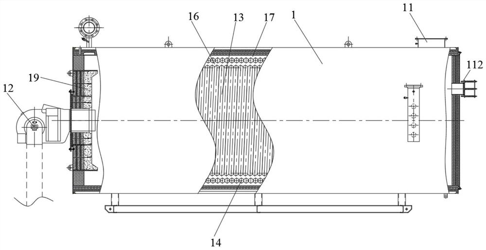
[0061] On the basis of embodiment 1 or embodiment 2, such as figure 2 As shown, the boiler host 1 is arranged in a horizontal arrangement, a burner 12 is arranged at the front of the boiler host 1, and a flue gas outlet 11 is arranged at the tail of the boiler host 1;

[0062] The boiler host 1 is provided with a spiral inner coil 13 and a spiral outer coil 14; The convection channel 16, the second convection channel 17 is surrounded by the spiral outer coil 14 and the shell of the boiler main engine 1; connected, the outlets of the spiral inner coil 13 and the spiral outer coil 14 are respectively communicated with the external oil outlet pipes; in addition, the fixing methods of the spiral inner coil 13 and the spiral outer coil 14 inside the main boiler 1 can be To achieve this, usually the distance tube 18 is fixedly arranged on the casing of the boiler main engine 1 .

[0063] In this application, the main engine 1 of the boiler adopts the spiral coil as the main heati...


PUM


Abstract

The invention discloses an energy-saving and environment-friendly heat-conducting oil boiler which includes a boiler main machine, a waste heat boiler and an air preheater. The waste heat boiler includes a vertical body; the vertical body is internally provided with a vertical snakelike heat exchange tube, and the straight pipe section of the vertical snakelike heat exchange pipe is inclined upwards; an upper outlet of the vertical snakelike heat exchange pipe communicates with a steam inlet of a steam drum; a common downcomer is arranged at the bottom of the steam drum, and a steam outlet pipe seat is arranged at the top of the steam drum; the air preheater includes an outer frame, and a plurality of vertical heat exchange pipes are arranged inside the outer frame; a flue gas outlet of the boiler main machine is connected with a flue gas inlet in the top of the waste heat boiler; and the flue gas outlet in the bottom of the waste heat boiler communicates with the vertical heat exchange pipes in the air preheater. The final exhaust gas temperature of the boiler can be effectively reduced by installing a two-stage energy-saving device including the waste heat boiler and the air preheater at the tail end of the boiler main machine, so that the final exhaust gas temperature of the boiler is not higher than 100 DEG C, and the thermal efficiency of the boiler is greatly improved.

Description

technical field [0001] The invention belongs to the technical field of boilers, and in particular relates to an energy-saving and environment-friendly heat-conducting oil boiler. Background technique [0002] Heat-conducting oil boiler refers to a boiler that uses heat-conducting oil as the heat-carrying medium. Generally, coal, oil, and gas are used as fuel, and heat-conducting oil is used as the heat-carrying medium. Phase circulation, the heat energy is delivered to the heat-consuming equipment and then returned to the heating furnace for reheating, which can obtain a higher working temperature under a lower working pressure and save steel. Since the temperature of the medium in the heat transfer oil boiler is relatively high, usually 260-320°C, the exhaust gas temperature of the boiler is also relatively high, usually above 300°C, resulting in waste of energy and low thermal efficiency. [0003] Therefore, there is an urgent need to design an energy-saving and environme...

Claims


Application Information

Patent Timeline
IPC IPC(8): F24H7/00F28D7/08F28F9/24F22B1/18F22B31/08F23J15/06F23L15/02F28D7/16
CPCF22B1/18F22B31/08F23J15/06F23L15/02F24H7/00F28D7/082F28D7/16F28F9/24Y02E20/34
Inventor 李宗兵岳东方李阳
Owner QINGDAO FERROLI HEATING & VENTILATION & TEMPERATURE CONTROL TECH EQUIP MFG CO LTD
Learn More