
Glass blind hole machining method

A processing method and glass technology, applied in the manufacture of electrical components, electrical solid devices, semiconductor/solid devices, etc., can solve the problems of low cost and low process temperature, and achieve the effects of high adhesion, high deposition quality, and low leakage

Active Publication Date: 2020-10-23
UNIV OF ELECTRONICS SCI & TECH OF CHINA +1
View PDF24 Cites 3 Cited by
  • Summary
  • Abstract
  • Description
  • Claims
  • Application Information

AI Technical Summary

Problems solved by technology

[0010] It can be seen that there is still a lack of preparation solutions that not only meet the development trend of future TGV miniaturization and high-frequency applications, but also take into account high versatility, low process temperature, compatibility with traditional CMOS processes, and low cost.

Method used


Image

  • Glass blind hole machining method
  • Glass blind hole machining method
  • Glass blind hole machining method

Examples


Embodiment 1

[0101] Glass-based blind vias were fabricated using the following steps:

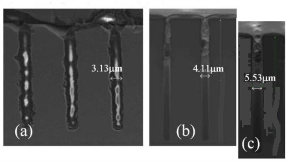
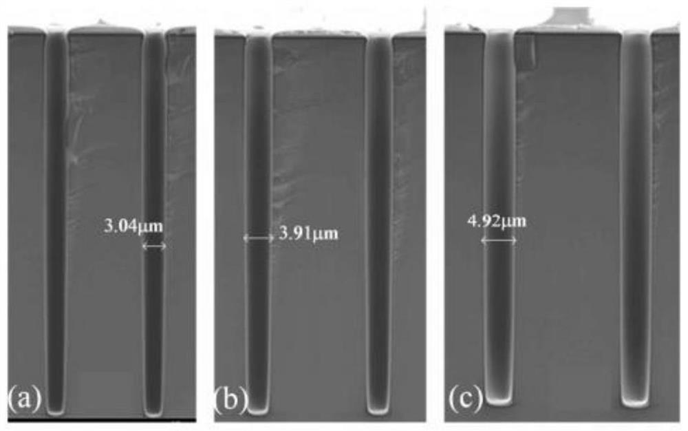
[0102] a. Etch blind holes with a diameter of 3 μm and a depth of 45 μm on the front of the glass, and the number of blind holes is 25*25;

[0103] b. Adhesion layer deposited on the side wall of the deep hole:

[0104] b1, the PI-5J polyimide solution that the viscosity is 1200cP is drip-coated on the glass surface, guarantees that the high polymer solution covers the glass surface;

[0105] b2. Transfer the glass to an environment with an air pressure of 100Pa, and let it stand for 10 minutes to make the polymer solution fill the deep hole;

[0106] b3. Fix the glass on the turntable, the center of the glass deviates from the center of rotation of the turntable, drive the turntable to rotate, the glass center line speed is 2000rpm, the rotation time is 30s, and the polymer solution on the glass surface and in the deep hole is thrown off;

[0107] b4. Drying to solidify the polymer solution remaining...


PUM

PropertyMeasurementUnit
thicknessaaaaaaaaaa
thicknessaaaaaaaaaa
thicknessaaaaaaaaaa

Abstract

The invention provides a glass blind hole machining method. The glass blind hole machining method comprises the steps of: a, carrying out deep hole etching; b, depositing an adhesion layer on the sidewalls of deep holes: b1, dispensing a high polymer solution on the surface of a glass substrate to ensure that the high polymer solution covers the surface of the glass substrate; b2, transferring the glass substrate to an environment of which the pressure is lower than atmospheric pressure, and standing the glass substrate so that the deep holes are filled with the polymer solution; b3, fixing the glass substrate to a rotary disc, and driving the rotary disc to rotate to thrown away the high polymer solution on the surface of the glass substrate and in the deep holes, wherein the center of the glass substrate deviates from the rotation center of the rotary disc; b4, drying to cure the residual high polymer solution on the surface of the glass substrate and the side walls of the deep holes to form a high polymer adhesive film; c, depositing a seed layer on the side walls; d, filling copper in the deep holes; and e, conducting surface CMP and RDL wiring manufacturing. The TSV preparedby adopting the glass blind hole machining method has high thermal-mechanical reliability and excellent electrical properties, can be used for processing deep holes with the aperture of 3 microns andthe depth of 45 microns, and conforms to the development trend of TSV miniaturization.

Description

technical field [0001] The invention relates to the technical field of manufacturing a three-dimensional integrated package adapter board, in particular to a method for processing a glass blind hole. Background technique [0002] 3D packaging is currently the most mature integration category in the industry. It mainly stacks bare chips or individually packaged chips together through packaging. It currently includes many different technologies, most of which are the extension of existing single-chip packaging technology to the three-dimensional direction. . The interposer, also known as the insertion layer or the middle layer, is a new type of electronic substrate that can realize the connection between the fine-pitch I / O at the top die level and the larger-sized and large-pitch I / O at the bottom package level. interconnection between. The glass transfer board is a new type of transfer board. There are many glass blind vias on the glass transfer board. The glass blind vias ...

Claims


Application Information

Patent Timeline
Patent Type & Authority Applications(China)
IPC IPC(8): H01L21/768H01L23/532
CPCH01L21/76802H01L21/76831H01L21/76877H01L21/76873H01L23/5329
Inventor 方针陈宏伟高莉彬张继华陈雨哲曲胜邹思月王文君蔡星周穆俊宏
Owner UNIV OF ELECTRONICS SCI & TECH OF CHINA
Learn More