Photovoltaic cell module
A technology of photovoltaic cells and unit modules, applied in photovoltaic modules, photovoltaic power generation, support structures of photovoltaic modules, etc., can solve the problems of increasing reflected light, inconvenient transmission and storage, and improving power generation efficiency without disclosure.
- Summary
- Abstract
- Description
- Claims
- Application Information
AI Technical Summary
Problems solved by technology
Method used
Image
Examples
Embodiment approach 1
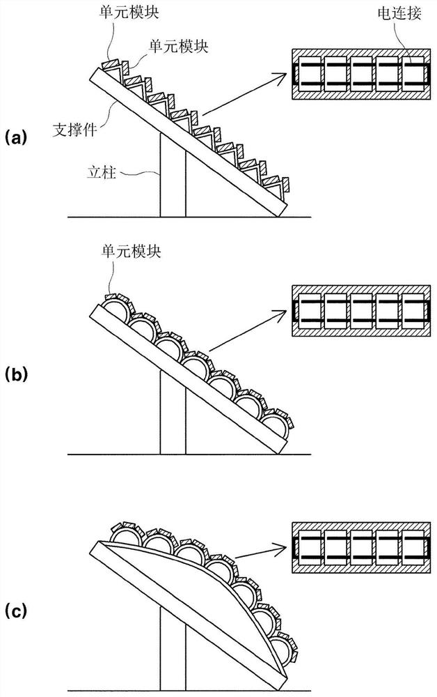
[0103] will use figure 1 (a) to (c) describe the configuration of the module according to the first embodiment of the present invention.
[0104] figure 1 (a) is a diagram showing a configuration of a module in which a plurality of rectangular unit modules are mounted on a support including a bent portion having a triangular pipe shape at an upper portion thereof.
[0105] The support including the triangular protrusion is built on an installation site such as a plain, a slope, a roof, an outdoor facility, or a public house. The support includes a post supported by the ground or wall surface and a support connected to the post and including a triangular protrusion. A photovoltaic cell module is mounted on the surface of the triangular protrusion.
[0106] like figure 1 As shown in (a) of (a), the photovoltaic cell unit module is configured such that a plurality of photovoltaic cells are arranged in a row, and surface electrodes and rear electrodes of cells adjacent to each...
Embodiment approach 2
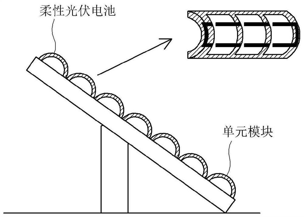
[0117] figure 2 is a diagram illustrating a method of using a flexible photovoltaic cell that can obtain a curved surface effect by using a typical flat support.
[0118] Flexible photovoltaic cells include thin silicon photovoltaic cells and thin film photovoltaic cells. That is, since conventionally commonly used silicon photovoltaic cells have a wafer thickness of about 180 μm, the silicon photovoltaic cells have insufficient flexibility and elasticity and thus are easily broken during bending. However, when thin-film silicon cells are applied, the wafer thickness can be reduced to 100 μm or less, and flexibility and elasticity can be increased. Therefore, bending equal to or greater than 60° can be performed.
[0119] Thin Film Photovoltaic Cells Flexible photovoltaic cells can be manufactured by using a metal substrate such as a polymer sheet or a stainless steel sheet as a substrate so that the shape of the cell can be easily deformed.
[0120] Therefore, when a thin...
Embodiment approach 3
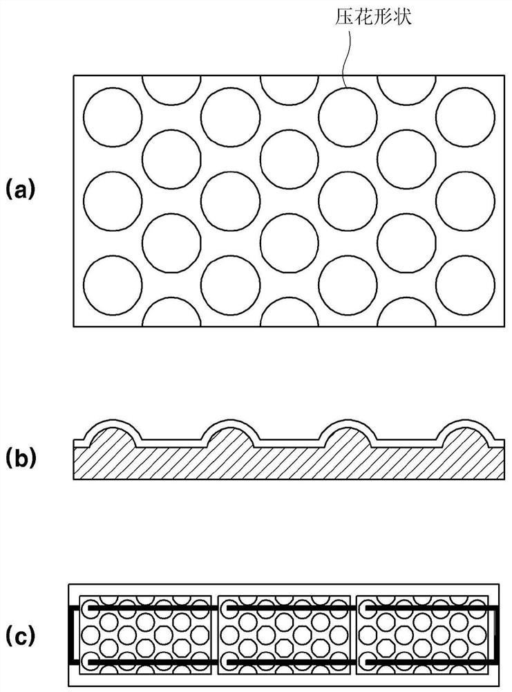
[0124] image 3 is a diagram showing a thin film photovoltaic cell manufactured on a flexible substrate including a plurality of uneven portions through an embossing process and a unit module including the thin film photovoltaic cell.
[0125] The embossing treatment method includes forming multiple embossments on the surface of a substrate by using an apparatus for treating embossing on the surface of a polymer sheet such as polyimide or a metal sheet such as a stainless steel sheet, copper sheet, and zinc sheet. method for uneven parts. The embossing treatment method can generally be carried out in the following manner: a flexible substrate is inserted between and passes through the upper and lower embossing rollers, and the embossing formed on the outer peripheral surface of the rollers is removed by applying heat or pressure. Or the embossing is transferred to the substrate to form a plurality of uneven parts. In addition, embossing processing methods include laser engra...
PUM
| Property | Measurement | Unit |
|---|---|---|
| angle | aaaaa | aaaaa |
| diameter | aaaaa | aaaaa |
Abstract
Description
Claims
Application Information
 - R&D
- Intellectual Property
- Life Sciences
- Materials
- Tech Scout
- Unparalleled Data Quality
- Higher Quality Content
- 60% Fewer Hallucinations
Browse by: Latest US Patents, China's latest patents, Technical Efficacy Thesaurus, Application Domain, Technology Topic, Popular Technical Reports.
© 2025 PatSnap. All rights reserved.Legal|Privacy policy|Modern Slavery Act Transparency Statement|Sitemap|About US| Contact US: help@patsnap.com


