Automatic shot indication and trajectory measurement system for relevant double-sampling linear array sensor

A line array sensor and correlated double sampling technology, applied in target indication system, measuring device, target, etc., can solve the problems of large structure, poor detection performance of high-speed projectiles, and unobvious dark spots, etc., to reduce data transmission Or the effect of processing pressure, detection accuracy higher than the target time, and simplifying the structure of software and hardware

Active Publication Date: 2020-11-06
张劲
View PDF10 Cites 4 Cited by
  • Summary
  • Abstract
  • Description
  • Claims
  • Application Information

AI Technical Summary

Problems solved by technology

It is also possible to replace the receiving tube with an ultra-high sensitivity line array camera or a line array sensor for detection, that is, the high-sensitivity dual line array camera intersection method. The former is a shooting auxiliary training room based on a high-speed industrial camera in CN201910505380. One or more high-sensitivity high-speed industrial line-scan cameras can shoot dozens of KHz per second, such as the line-scan cameras of DALSA, Canada, which are realized with professional acquisition cards. The data transmission and processing pressure is high and the price is expensive. It can still maintain a high positioning accuracy in the case of the projectile, but it cannot measure the moment when the projectile passes the target; the latter has several forms, one is with an imaging structure, and the infrared light source and the line array sensor with the imaging structure are located at the projectile to be tested. On both sides, such as CN201510487949.3's automatic target reporting and speed measuring device and its positioning and speed measuring method, it can accurately locate projectiles other than tracer bullets, and can roughly measure the moment when the projectile passes the target by adding a second type of optical sensor. The error is equivalent to the exposure period of the second type of optical sensor. Since the carrier modulation cannot be used, and the sunlight reflected when the projectile passes the target is also received by the line array sensor, the detection dark spot is "filled up", so the outdoor sunlight The anti-interference ability of infrared light is poor, and the interference can only be reduced by increasing the brightness of the background infrared light source and increasing the structure of the extinction spiral. The sensitivity of the line array sensor required by this method needs to be much higher than that of the ordinary line array CCD. The corresponding pixel Excessively large sensing surface is too long and the larger extinction spiral leads to a larger structure. For example, TSL208 has only 640 pixels but is 64mm long. At the same time, this solution requires the sensor to work in the continuous exposure mode in which the entire scanning period is in the exposure state, so the limitation The selection range of the sensor is defined; the other is without imaging structure, and the infrared light source and the line array sensor on the side of the target surface are also located on both sides of the projectile to be tested, such as a kind of laser target reporting device and method of CN201810599455.8, However, it is required that the sensing surface of a single line array sensor used is super long. In fact, only CIS line array sensors are available and can only be spliced ​​to form the side of the target surface.
The intersection method of high-sensitivity dual line array cameras is detected by the projectile located between the line array sensor and the background light source blocking the background light source, which requires that the detectable time of the projectile passing through the target surface accounts for a considerable part of the exposure time to obtain a more obvious detection Dark spots, and work in the continuous exposure mode in which the exposure time continuously occupies the entire sensor scanning period to avoid missing scans, so the dark spots are very inconspicuous, resulting in poor detection performance for high-speed projectiles

Method used


Image

  • Automatic shot indication and trajectory measurement system for relevant double-sampling linear array sensor
  • Automatic shot indication and trajectory measurement system for relevant double-sampling linear array sensor
  • Automatic shot indication and trajectory measurement system for relevant double-sampling linear array sensor

Examples


Embodiment 2

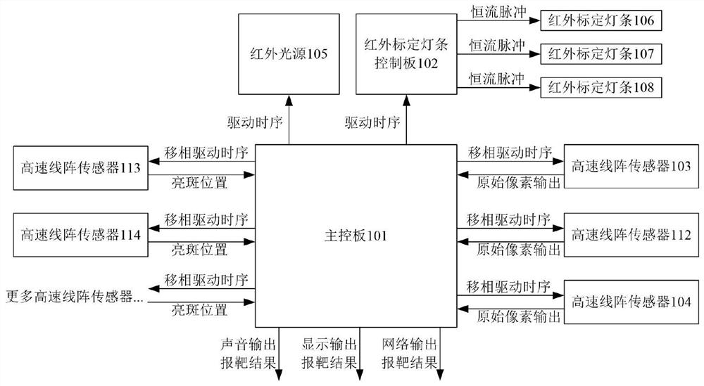
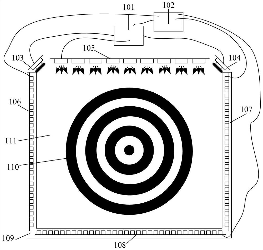
[0083] Compared with Embodiment 1, in addition to two high-speed line array sensors 103 and 104 installed on the sides other than the three side frames, embodiment 2 also adds a high-speed line array sensor 112, and the lens assembled by the sensor matches the angle of view of the sensor It is larger than 103 and 104, and it also needs to cover the target surface area. If a 2.3mm lens is used, a fan-shaped viewing angle range of not less than 122 degrees can be obtained, which is greater than 89 degrees of 103 and 104. In addition, the control timing of the three line array sensors in Embodiment 2 is also different from Embodiment 1. In Embodiment 1, 103 and 104 are as follows: Figure 4 As shown, the same control sequence is used, and in Embodiment 2, 103, 112, and 104 adopt a phase-shifted control sequence, so that at any moment, the non-exposure time of one sensor is covered by the exposure time of the other two sensors, that is Regardless of the moment when the projectile ...

Embodiment 1

[0093] Embodiment 1 and Embodiment 2 both only involve the positioning method of the coordinates of the projectile passing the target, and the method for measuring the moment of the projectile passing the target will be described below through Embodiment 3. Embodiment 3 also adopts the method of phase shifting, but compared with Embodiment 2, more high-speed line array sensors are used. The establishment method of the optical calibration table, the double-sampling CDS mode and the hardware selection method of the bright spot data in the third embodiment are the same as those in the first and second embodiments. Thanks to the method of selecting bright spot data by the hardware to reduce the pressure of data transmission and processing, embodiment 3 can use more high-speed linear array sensors to improve the measurement accuracy of the time when the projectile passes the target. For embodiment 3, in theory, when using n sensors, in the case of a high-speed projectile (the time ...

Embodiment 3

[0095] Embodiment 3 is described in detail below. The method of Embodiment 3 of the present invention is a method for detecting the position of the target and the moment of passing the target of various speed projectiles, comprising the following steps:

[0096] Step 1: The main control board controls the infrared light source to be turned off, and the infrared calibration light bar control board is used to control the infrared calibration light bar to light up chain by chain, that is, each light chain is turned off after multiple scanning cycles, and the output of the main control board is shifted. Drive the logic to N>3 high-speed line array sensors, but only collect the images of each light chain sequentially lit by 3 of the sensors that return the original pixel output. The phase shift phase of the original pixel acquisition sensor must be guaranteed, The non-exposure time of any high-speed line array sensor among the three sensors that return the original pixel output is c...


PUM


Abstract

The invention provides an automatic shot indication and trajectory measurement system for a relevant double-sampling linear array sensor. For a low-speed projectile, at least two high-speed linear array sensors are used for detecting the position of a position of a shot, at least three phase-shift high-speed linear array sensors are used for a high-speed projectile, and more sensors are used for shortening phase-shift time to detect the position of the position of the shot and a target passing moment. The automatic shot indication and trajectory measurement system adopts a reflection type light source, projectiles are used for reflecting a light spot for detection, a bullet category is not restricted, and infrared light interference is resisted. The invention also adopts a calibration light bar to carry out self-adjustment, and an irreversible deformation error can be eliminated. By use of the scheme, relevant double sampling is adopted to eliminate the null point and the drift of thelinear array sensor, individual adjustment is not required, and a situation that multiple periods of initial data are required to eliminate the null point and the drift is avoided. An automatic threshold value method for solving a bright spot coordinate can be easily realized through hardware, including FPGA (Field Programmable Gate Array) and the like, data transmission and processing pressure are reduced, and the automatic shot indication and trajectory measurement system is favorable for utilizing a plurality of linear array sensors to improve measurement accuracy of the target passing moment.

Description

technical field [0001] The invention belongs to the technical field of digital shooting target reporting, and in particular relates to an automatic target reporting and ballistic measurement system of a correlated double-sampling linear array sensor. Background technique [0002] Target shooting is an indispensable item in shooting competitions and military training. There are problems of poor safety and timeliness in manual target reporting. The automatic intelligent target reporting system can improve efficiency and accuracy, and effectively ensure personnel safety. By connecting multiple automatic target reporting devices that are hollowed out in the middle of the target surface along the ballistic trajectory of the projectile and can accurately measure the time and position coordinates of the projectile passing the target, a ballistic measurement system can also be formed to provide strong support for criminal investigation and gun calibration. The existing automatic t...

Claims


Application Information

Patent Timeline
Patent Type & Authority Applications(China)
IPC IPC(8): F41J5/02F41J5/14G01B11/00
CPCF41J5/02F41J5/14G01B11/002
Inventor 张劲
Owner 张劲
Why Eureka
Try Eureka