
Switch hybrid resonance circuit and switch hybrid resonator

A resonant circuit and switch technology, applied in the field of electronics, can solve the problems of easy harmonic interference, large circuit peak interference and heat generation, easy burnout of devices, etc., to improve anti-interference ability, superior heat dissipation performance, and prolong service life. Effect

Active Publication Date: 2020-11-06
湖南华鑫晶造电气科技有限公司
View PDF13 Cites 0 Cited by
  • Summary
  • Abstract
  • Description
  • Claims
  • Application Information

AI Technical Summary

Problems solved by technology

[0002] A frequency of 20KHZ to 400KHZ is widely used in semiconductor, solar photovoltaic, industrial coating, plasma cleaning, nanomaterial processing, material surface modification and other industries The sine wave high-power power supply, in order to meet the requirements of the above-mentioned industrial equipment, adopts a switch hybrid resonant circuit and a switch hybrid resonator to convert the square wave output by the previous switch circuit into a sine wave with small harmonic components and low spurious noise. The output power of the required power supply is thousands to tens of kilowatts. In the existing switching hybrid resonant circuit and switching hybrid resonator, the switching power tube, the inductor, capacitor and transformer in the hybrid resonant circuit will bear a large current and power. At the same time, switching power transistors, resonant inductors, capacitors and transformers at all levels and the connections between the levels flow dozens of hundreds of amperes of high-frequency current, which causes the circuit to generate large peak interference and heat, and is also prone to harmonics. Interference, thus affecting the normal use of the circuit
Switching power transistors, inductors, capacitors, transformers and other components in the existing switching hybrid resonators are often due to problems with the installation structure, and the wiring of the components between the levels is messy, resulting in unstable power output waveform frequency, and the components are easy to burn out

Method used


Image

  • Switch hybrid resonance circuit and switch hybrid resonator
  • Switch hybrid resonance circuit and switch hybrid resonator
  • Switch hybrid resonance circuit and switch hybrid resonator

Examples


Embodiment 1

[0041] Working principle of the present invention:

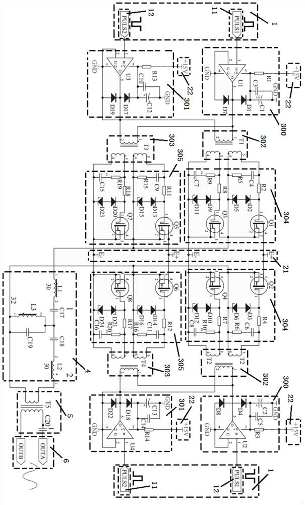
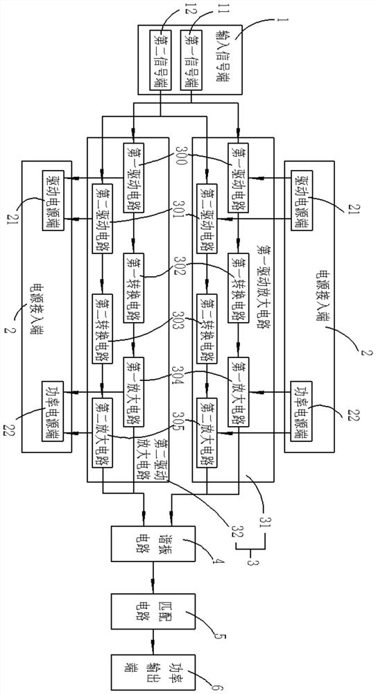
[0042]The first signal terminal 11 and the second signal terminal 12 are connected to a square wave signal of the required frequency, and the driving power supply terminal 21 of the power supply access terminal 2 provides the first driving circuit 300 and the second driving circuit 301 in the power amplifier circuit 3. The power supply drives the square wave signals connected to the first signal terminal 11 and the second signal terminal 12 to respectively enter the first conversion circuit 302 and the second conversion circuit 303 in the first drive amplifier circuit 31 and the second drive amplifier circuit 32 , the first conversion circuit 302 and the second conversion circuit 303 perform matching induction, and the induction signal is sent to the first amplifier circuit 304 and the second amplifier circuit 305 to drive the first transistor and the second transistor to work; the first amplifier circuit 304, the second tran...


PUM


Abstract

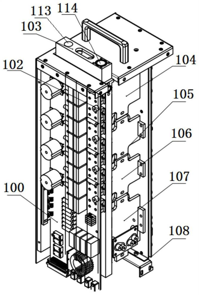
The invention discloses a switch hybrid resonance circuit, which comprises a signal input end, a power supply access end, a power amplification circuit, a resonance circuit, a matching circuit and a power output end. The signal output end is electrically connected with the signal end of the power amplification circuit, the output end of the power amplification circuit is electrically connected with the input end of the resonance circuit, the output end of the resonance circuit is electrically connected with the input end of the matching circuit, and the input end of the matching circuit is electrically connected with the power output end. The switch hybrid resonator is suitable for installing the switch hybrid resonance circuit, and comprises a shell and a radiator arranged in the shell, and the radiator divides the interior of the shell into a power amplification area, a resonant inductance area and an output area. The power amplifier has the advantages of being stable in power outputfrom 10 KW to 80 KW, high in circuit anti-interference performance, stable in output waveform frequency, simple in installation structure, compact in installation of all components and parts and excellent in circuit heat dissipation performance.

Description

technical field [0001] The invention belongs to the field of electronic technology, and in particular relates to a switch hybrid resonant circuit and a switch hybrid resonator. Background technique [0002] A sine wave high-power power supply with a frequency of 20KHZ to 400KHZ is widely used in equipment in semiconductor, solar photovoltaic, industrial coating, plasma cleaning, nano-material processing, material surface modification and other industries. In order to meet the requirements of the above-mentioned industry equipment, adopt The switch hybrid resonant circuit and the switch hybrid resonator convert the square wave output by the previous stage switch circuit into a sine wave with small harmonic components and low spurious noise. Since the output power of the power supply required by the equipment is several thousand to tens of kilowatts, in the present In some switching hybrid resonant circuits and switching power tubes in switching hybrid resonators, the inductor...

Claims


Application Information

Patent Timeline
Patent Type & Authority Applications(China)
IPC IPC(8): H02M1/44H02M1/088H05K7/20
CPCH02M1/44H02M1/088H05K7/20927Y02B70/10
Inventor 杨建生孙雪平张朝阳张彬庭
Owner 湖南华鑫晶造电气科技有限公司
Learn More