Working method for sewage treatment fluid control device

A technology for controlling equipment and sewage treatment, applied in water/sewage treatment equipment, water treatment parameter control, water/sewage treatment, etc. Improve mixing efficiency and improve the effect of mixing effect

Active Publication Date: 2020-11-13
RAILWAY NO 5 BUREAU GRP FIRST ENG CO LTD +2
View PDF6 Cites 2 Cited by
  • Summary
  • Abstract
  • Description
  • Claims
  • Application Information

AI Technical Summary

Problems solved by technology

[0004] 1. In the prior art, when the pharmacy is feeding the flocculation reaction tank, due to the large range of the flocculation reaction tank, it is difficult to evenly cover the entire reaction tank when feeding the drug, so it is difficult to achieve the effect of uniform reaction flocculation
[0005] . In the existing technology, when the pharmacy is used to feed the flocculation reaction tank, more than one kind of medicine is often applied. After the medicine is fully mixed, the flocculation effect is improved. However, in the prior art, two kinds of medicines are often poured into a reaction tank and then mixed. The degree of automation Poor and cumbersome flow control
[0006] 1. In the prior art, when the pharmacy feeds the flocculation reaction tank, ordinary ball valves are often used to control the flow rate. However, the opening control of the ball valve is not accurate and cannot be quantified. The reasons are as follows: the opening of the ball valve is not a linear change As the ball valve rotates, the change of the opening area is not a linear increase / decrease, but a curve or step change. Therefore, although the opening and flow can be controlled, it cannot be precisely controlled and quantitatively controlled.
[0007] 1. The one-way valve in the prior art has a return spring, so that the one-way valve is closed when the pressure is not enough to open the one-way valve. However, this will easily cause the liquid that cannot flow out to remain, and in severe cases, it will cause a certain amount of water hammer, and if the liquid remains It is also a detriment to the precision control
[0008] , The confluence of the existing technology is often in the form of a zipper confluence, which causes a certain amount of water hammer and affects the life of the equipment
[0009] 1. The swirling disc of the prior art has a weaker converging effect and a relatively weaker mixing effect

Method used


Image

  • Working method for sewage treatment fluid control device
  • Working method for sewage treatment fluid control device
  • Working method for sewage treatment fluid control device

Examples


Embodiment Construction

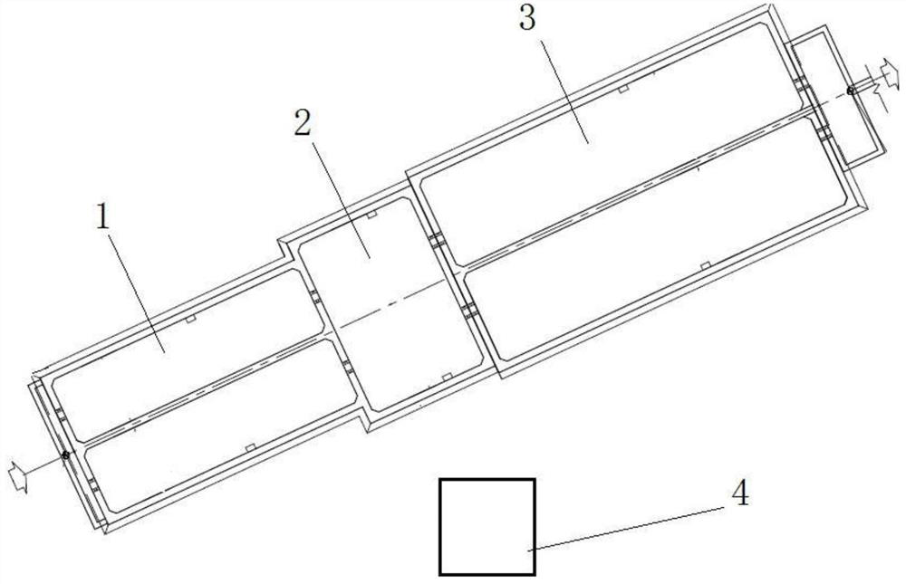
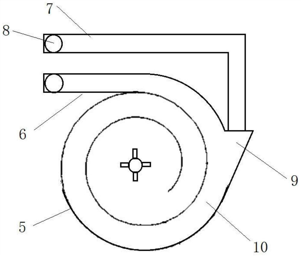
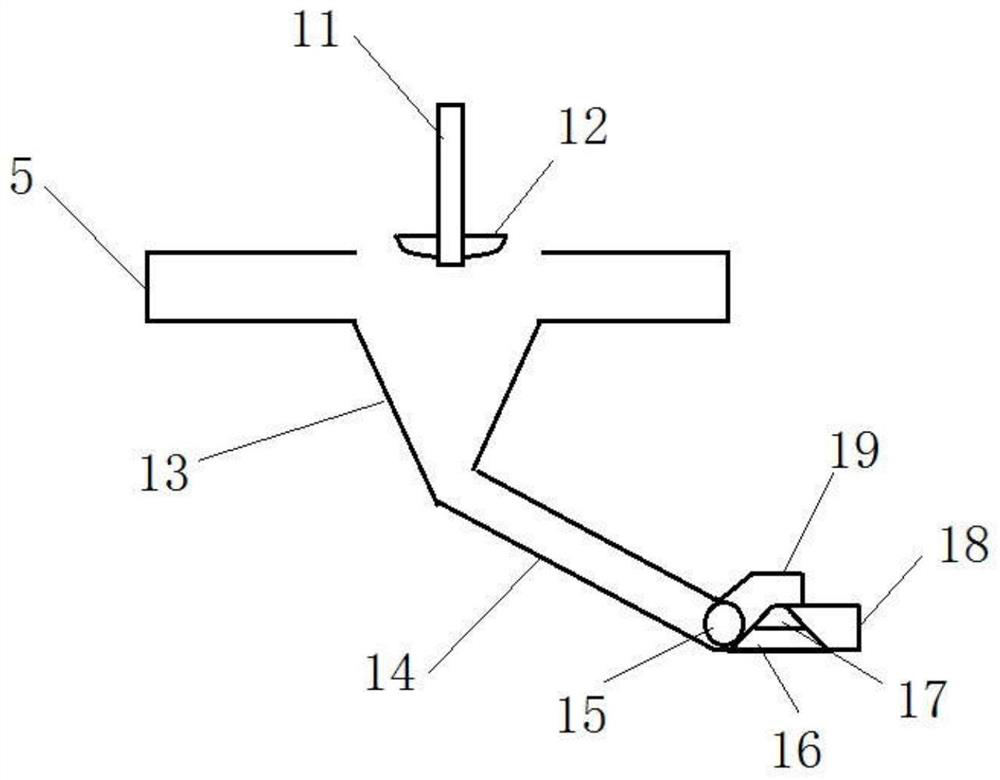
[0042] As shown in the figure: a working method of sewage treatment fluid control equipment, the sewage treatment fluid control equipment includes: swirl disc, first dosing pipe, second dosing pipe, control ball valve, confluence cone pipe, stirring rod , stirring blade, funnel, inclined flow channel, one-way valve ball, drainage channel, blocking block, inflow pipe, relief pipe head, liquid level sensor, controller; wherein the control ball valve includes a valve body, a ball, a valve Rod, sealing valve seat, valve neck, the ball includes a small flow channel, a large flow channel, the first zone, the second zone, the third zone, the fourth zone, the fifth zone, the sixth zone, the seventh zone, the first zone Eighth zone, the large flow channel includes the first port and the second port, and the small flow channel includes the third port and the fourth port; the working method includes: controlling the flow control method of the ball valve and the linkage control method;

...


PUM


Abstract

The invention discloses a working method for a sewage treatment fluid control device. The sewage treatment fluid control device comprises a rotational flow disc, a first charging pipe, a second charging pipe, a control ball valve, a flow collection conical pipe, a stirring rod, a stirring blade, a funnel, an inclined flow channel, a one-way valve ball, a drainage channel, a blockage block, a flowinlet pipe, a yielding pipe end, a liquid level sensor and a controller, wherein the control ball valve comprises a valve body, a ball body, a valve rod, a sealing valve base and a valve neck; the ball body comprises a small-flow channel, a large-flow channel, a first area, a second area, a third area, a fourth area, a fifth area, a sixth area, a seventh area and an eighth area; the large-flow channel comprises a first port and a second port; and the small-flow channel comprises a third port and a fourth port. The working method comprises a ball valve circulation control method and a linkage control method.

Description

technical field [0001] The invention relates to the field of tunnel engineering drainage, in particular to a working method of sewage treatment fluid control equipment. Background technique [0002] The tunnel construction project in the prior art is partly located in the water environment sensitive area of ​​the river basin, with a large line span, a wide range of strong karstification strata, and far-reaching interactive effects on the water environment. Surface engineering construction sewage may seep through the tunnel drainage holes, and groundwater iron and manganese may exceed the standard in some sections of the tunnel; in addition, due to the high requirements for water and soil conservation in areas such as engineering construction slag yards and construction sites. There are high requirements for engineering environmental protection and water and soil conservation, and there are also requirements for tunnel construction projects, so drainage becomes particularly i...

Claims


Application Information

Patent Timeline
Patent Type & Authority Applications(China)
IPC IPC(8): F17D1/08F17D3/01F17D3/12F16K5/06F16K5/08F16K5/12F16K5/20C02F1/52C02F1/00
CPCC02F1/008C02F1/5281C02F2201/002C02F2209/42F16K5/0605F16K5/08F16K5/12F16K5/201F17D1/08F17D3/01F17D3/12
Inventor 黄苛罗运杰杨文国段鹏昌彭学军尹来容刘冬雯杨雄杨自刚汤宇胡旭盛黄光王渊段磊李强何林云童昌林巍杰凌涛
Owner RAILWAY NO 5 BUREAU GRP FIRST ENG CO LTD
Why Eureka
Try Eureka