Far infrared drying equipment

A technology of far-infrared drying and far-infrared radiant panels, which is used in drying solid materials, drying chambers/containers, drying gas layout, etc., can solve problems such as fire easily caused by open flames, reduce safety, and material pollution, and avoid drying efficiency. The effect of reducing and extending the moving distance and avoiding material contamination

Pending Publication Date: 2020-11-13
NANJING YUANCHANG ADVANCED MATERIAL CO LTD
View PDF1 Cites 0 Cited by
  • Summary
  • Abstract
  • Description
  • Claims
  • Application Information

AI Technical Summary

Problems solved by technology

These traditional infrared radiation devices have the following disadvantages: first, the energy consumption is high, and far-infrared rays must be emitted at a certain high temperature; second, the energy utilization rate of the far-infrared radiation heater is heated by burning coal, oil and natural gas Low, and due to insufficient combustion of fuel, it will also cause certain pollution to the environment; third, the use of fuel-powered infrared radiation heaters, not only the temperature is difficult to control during the drying process, but also the use of open flames is easy to cause fires, so the safety is poor
However, since there is no protective layer on the outside of the infrared coating on the infrared radiation light wave plate, the infrared coating material will inevitably fall off during long-term use, resulting in reduced drying efficiency and material contamination
Moreover, this design increases the structural complexity and cost of the device, while reducing safety and increasing the failure rate of the device

Method used


Image

  • Far infrared drying equipment
  • Far infrared drying equipment
  • Far infrared drying equipment

Examples


Embodiment Construction

[0029] In order to make the content of the present invention more clearly understood, the present invention will be further described in detail below based on the specific embodiments and in conjunction with the accompanying drawings.

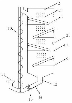
[0030] This embodiment provides a far-infrared drying device, which includes a drying box 1 , and a drying chamber 2 for drying materials is arranged in the drying box 1 . The upper part of the drying chamber 2 is provided with an entrance. On the left side wall and the right side wall in the drying chamber 2, several far-infrared radiation plates 3 are arranged alternately from top to bottom. The free ends of these far-infrared radiation plates 3 are all inclined downward, and each far-infrared radiation The free ends of the plates 3 all extend above the far-infrared radiation plates 3 located below them. The material to be dried automatically falls to the next far-infrared radiation plate 3 after sliding along the far-infrared radiation plat...


PUM


Abstract

The invention discloses far infrared drying equipment and relates to the technical field of drying equipment. The far infrared drying equipment comprises a drying box body, wherein a drying chamber isarranged in the drying box body, a plurality of far infrared radiant panels are alternately arranged on two opposite inner side walls of the drying chamber in a staggered manner in a vertical direction. The free ends of the far infrared radiant panels incline downward. Each far infrared radiant panel successively comprises a supporting layer, a reflective layer, an infrared radiant layer and a wear-resistant layer from bottom to top. The far infrared radiant panel successively comprises the supporting layer, the reflective layer, the infrared radiant layer and the wear-resistant layer from bottom to top, wherein the supporting layer can support the dead weight of the far infrared radiant panel and the impact force of a material, and the reflective layer can reflect far infrared rays emitted by an infrared radiant layer to the upper surface of the far infrared radiant panel, so that the drying efficiency is improved. The wear-resistant layer can protect the infrared radiant layer, so that reduction of drying efficiency and material pollution due to wear of the infrared radiant layer after long-time use is avoided.

Description

technical field [0001] The invention relates to the technical field of drying equipment, in particular to a far-infrared drying equipment. Background technique [0002] The wavelength of far-infrared rays is between 4 and 400 microns, which can be directly heated from the inside of the material, which is conducive to the rapid evaporation of internal moisture. Compared with traditional hot air drying, far-infrared drying does not need to directly heat the air around the material, and has the advantages of high efficiency and energy saving, so it has been widely used in many fields. At present, the far-infrared drying equipment used on a large scale is mainly silicon carbide infrared radiation electric heater, milky white quartz infrared radiation electric heater, ceramic infrared radiation electric heater, resistance band infrared radiation electric heater and coal and flue gas infrared radiation heating device etc. These traditional infrared radiation devices have the fol...

Claims


Application Information

Patent Timeline
IPC IPC(8): F26B17/16F26B23/04F26B3/30F26B21/08F26B21/10F26B25/06
CPCF26B17/16F26B23/04F26B3/30F26B21/004F26B21/08F26B21/10F26B25/06
Inventor 黄盛杰李建稳曾培源何占宇沈健民
Owner NANJING YUANCHANG ADVANCED MATERIAL CO LTD
Why Eureka
Try Eureka