Circumferential powder feeding type plasma generator

A technology of plasma generator and powder feeder, which is applied in the direction of plasma, electrical components, spray discharge devices, etc., can solve problems such as deterioration, insufficient heating, and reduced bonding force between coating and substrate, and achieve optimal powder feeding position and Angle, improvement of coating forming quality, effect of reducing coating defects

Pending Publication Date: 2020-11-20
南通德邦新材料科技有限公司
View PDF2 Cites 1 Cited by
  • Summary
  • Abstract
  • Description
  • Claims
  • Application Information

AI Technical Summary

Problems solved by technology

If the distance between the powder feeding port and the end face of the nozzle is too small, it is likely to cause insufficient heating, poor powder melting, and reduced bonding force between the coating and the substrate
If the distance between the powder feeding port is too large, the powder will melt in advance and easily lead to larger droplets, which will lead to nozzle clogging and coating quality deterioration

Method used


Image

  • Circumferential powder feeding type plasma generator
  • Circumferential powder feeding type plasma generator
  • Circumferential powder feeding type plasma generator

Examples


Embodiment Construction

[0026] Various exemplary embodiments of the invention are now described in detail. It should be noted that the relative arrangements of components and steps, numerical expressions and numerical values ​​set forth in these embodiments do not limit the scope of the present invention unless specifically stated otherwise.

[0027] The following description of at least one exemplary embodiment is merely illustrative in nature and in no way taken as limiting the invention, its application or uses.

[0028] Techniques, methods and devices known to those of ordinary skill in the relevant art may not be discussed in detail, but where appropriate, such techniques, methods and devices should be considered part of the description.

[0029] In all examples shown and discussed herein, any specific values ​​should be construed as exemplary only, and not as limitations. Therefore, other instances of the exemplary embodiment may have different values.

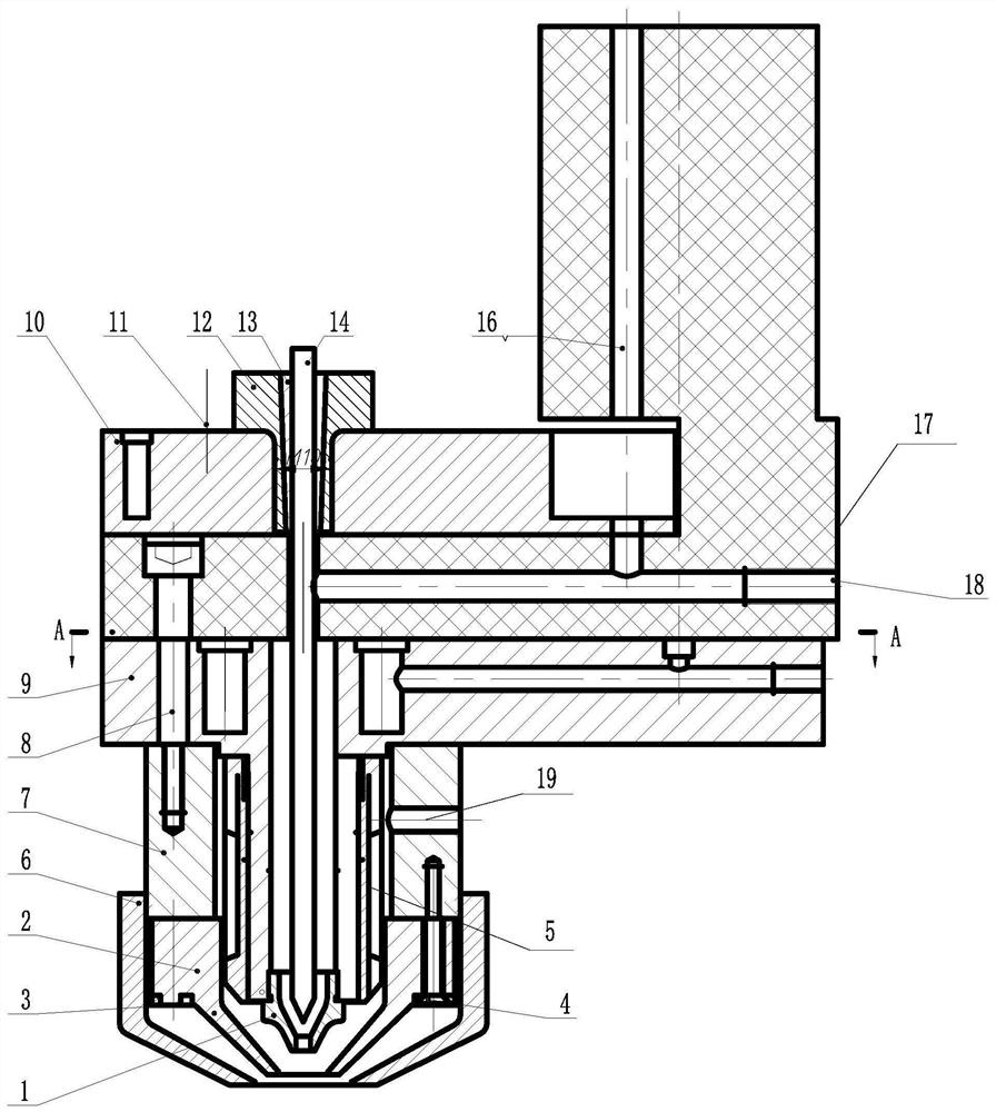
[0030] Such as figure 1 Shown, a kind...


PUM


Abstract

The invention discloses a circumferential powder feeding type plasma generator. The circumferential powder feeding type plasma generator comprises a nozzle, a lower gun body and an upper gun body, thelower gun body and the upper gun body are connected with an insulating block; a tungsten electrode penetrates through a tungsten electrode seat and extends to the lower part of the lower gun body; the tungsten electrode seat is fixed on the upper gun body through a fixing seat, and the tungsten electrode can move up and down relative to the lower gun body; the nozzle is arranged under the bottomend of the tungsten electrode, and a plasma torch chamber is arranged between the lower gun body and the nozzle; a powder distributor is connected with the upper gun body and the lower gun body, and the lower part of the powder distributor is connected with the nozzle; the powder distributor is communicated with a powder feeding pipe, and the powder feeding pipe is fixedly arranged on a powder blocking device; a powder feeder is arranged under the powder distributor, the powder feeder is communicated with the powder distributor, and the powder blocking device is arranged between the powder feeder and the bottom of the lower gun body; and outer covers are arranged outside the powder feeder and the powder second clamping parameter. By means of the optimized design of the powder distributor and the powder feeder, it is guaranteed that alloy powder is continuously fed into the plasma torch according to the preset proportion, the coating forming quality is improved, and the nozzle blockagephenomenon is avoided.

Description

technical field [0001] The invention belongs to the field of surface protection of engineering machinery parts, and in particular relates to a circular powder feeding type plasma generator. Background technique [0002] Corrosion wear is the main cause of failure of key friction pair parts of construction machinery. Among the many technologies to improve the wear resistance and corrosion resistance of materials, plasma cladding and spraying technology are widely used for their advantages of high efficiency, low consumption, and greenness. Plasma coating technology uses plasma beam irradiation to rapidly melt alloy powder or wire, and cladding a layer of material with special physical, chemical or mechanical properties on the surface of the substrate to form a new composite material to make up for the lack of the substrate. Lack of high performance, such as good wear resistance and corrosion resistance, etc. [0003] The plasma generator is the core component of the plasma ...

Claims


Application Information

Patent Timeline
Patent Type & Authority Applications(China)
IPC IPC(8): H05H1/26B05B5/025
CPCB05B5/025H05H1/26
Inventor 崔洪芝毕勇范平一李银俊赵剑波
Owner 南通德邦新材料科技有限公司
Why Eureka
Try Eureka