Method for repairing defects of lap joint positions of adjacent sub-areas formed by selective laser melting
A technology of laser selective melting and lap joint position, which is applied in the field of additive manufacturing engineering to achieve the effect of eliminating molten pool defects
- Summary
- Abstract
- Description
- Claims
- Application Information
AI Technical Summary
Problems solved by technology
Method used
Image

Examples
Embodiment 1
[0023] Example 1—Single-layer printing
[0024] (1) Use IN718 spherical powder, powder diameter 15-53um, fluidity 16s / 50g, D 50 32um, the substrate of laser selective melting equipment is preheated to 80°C for single-layer printing.
[0025] (2) The printing process is carried out in a protective atmosphere of Ar gas, and the oxygen content in the cabin is controlled below 200ppm.
[0026] (3) The parameters of laser selective melting are: laser power 195W, powder coating thickness 30um, substrate preheating temperature 80°C, scanning line spacing 70um, scanning strategy is laser bidirectional scanning, no strip overlap; scanning speed is 800mm / s, 900mm / s, 1000mm / s, 1100mm / s, 1200mm / s, 1300mm / s.
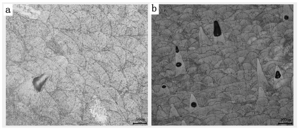
[0027] (4) Clean the substrate containing a single-layer printing layer with alcohol and place it under a microscope to observe the uniformity between the end of the melt channel and the inside of the melt, as shown in Figure 4 As shown, when the scanning speed is 800mm / s, 900m...
Embodiment 2
[0028] Example 2—Block Printing
[0029] (1) Using the materials and equipment used in Example 1, and the process parameters for single-layer printing, a 10x10x10mm IN718 block was printed.
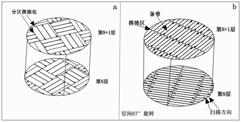
[0030] (2) Slice the formed parts with a thickness of 30um, plan the scanning path of the components, adopt strip-type bidirectional laser scanning, and set the laser jump speed of adjacent melting channels to 3000mm / s.
[0031] (3) The parameters of laser selective melting are: laser power 195W, powder coating thickness 30um, substrate preheating temperature 80°C, scanning line spacing 70um, interlayer rotation 67°, laser scanning speed 1000mm / s.
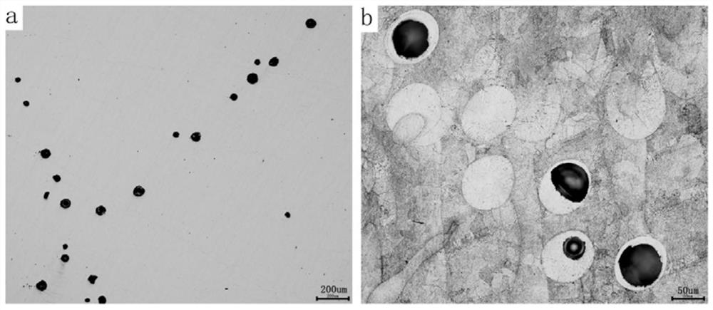
[0032] (4) The printed IN718 test block was removed from the substrate by wire cutting, and after ultrasonic cleaning, the density of the block was determined to be 99.0% by the Archimedes drainage method. Use wire cutting to cut the over-dense block along the forming direction and perpendicular to the forming direction in turn, and conduct m...
Embodiment 3
[0034] Example 3—Block Printing
[0035] (1) Using the materials and equipment used in Example 1, and the process parameters for single-layer printing, a 10x10x10mm IN718 block was printed.
[0036] (2) Slice the formed parts with a thickness of 30um, plan the scanning path of the components, adopt strip-type bidirectional laser scanning, and set the laser jump speed of adjacent melting channels to 4000mm / s.
[0037] (3) The parameters of laser selective melting are: laser power 195W, powder coating thickness 30um, substrate preheating temperature 80°C, scanning line spacing 70um, interlayer rotation 67°, laser scanning speed 1000mm / s.
[0038] (4) The printed IN718 test block was removed from the substrate by wire cutting, and after ultrasonic cleaning, the density of the block was determined to be 99.4% by the Archimedes drainage method. Use wire cutting to cut the over-dense block along the forming direction and perpendicular to the forming direction in turn, and conduct m...
PUM
 Abstract
Description
Claims
Application Information
 - R&D
- Intellectual Property
- Life Sciences
- Materials
- Tech Scout
- Unparalleled Data Quality
- Higher Quality Content
- 60% Fewer Hallucinations
Browse by: Latest US Patents, China's latest patents, Technical Efficacy Thesaurus, Application Domain, Technology Topic, Popular Technical Reports.
© 2025 PatSnap. All rights reserved.Legal|Privacy policy|Modern Slavery Act Transparency Statement|Sitemap|About US| Contact US: help@patsnap.com