Rear denitrification filter tank

A post-denitrification and denitrification technology, which is applied in anaerobic digestion treatment, chemical instruments and methods, special compound water treatment, etc. Achieve the effect of avoiding the increase of dissolved oxygen, reducing the dosage of carbon source, and high volume load

Pending Publication Date: 2020-11-27
四川省科学城天人环保有限公司
View PDF0 Cites 2 Cited by
  • Summary
  • Abstract
  • Description
  • Claims
  • Application Information

AI Technical Summary

Problems solved by technology

After sewage pretreatment and secondary biochemical treatment, there are still a large amount of nitrate nitrogen and nitrite in the tail water. It is not enough to increase the removal rate of total nitrogen only by increasing the reflux of nitrifying liquid. Therefore, further Perform denitrification and denitrification treatment
[0003] Most of the existing denitrification technologies use denitrification deep-bed filters and active sand filters, which are characterized by the fact that the filter material is quartz sand with a small particle size and is easy to lose; For denitrification and denitrification, due to the addition of external carbon sources, a certain amount of microorganisms will be generated, which will easily cause blockage of the filter material, reduce the amount of treated water, and the removal effect of total nitrogen is limited; in addition, there are difficulties in operation and management, complicated operations, and high treatment costs. , large area and other issues

Method used


Image

  • Rear denitrification filter tank
  • Rear denitrification filter tank
  • Rear denitrification filter tank

Examples


Embodiment Construction

[0027] The present invention is further described below in conjunction with specific embodiment, and specific embodiment is the further description of the principle of the present invention, does not limit the present invention in any way, and the identical or similar technology of the present invention all does not exceed the scope of protection of the present invention.

[0028] In conjunction with the accompanying drawings.

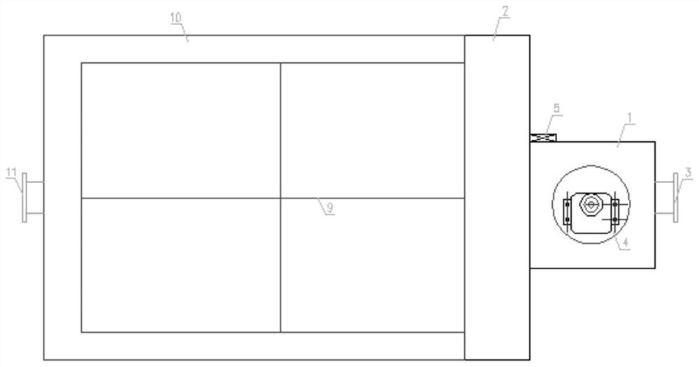
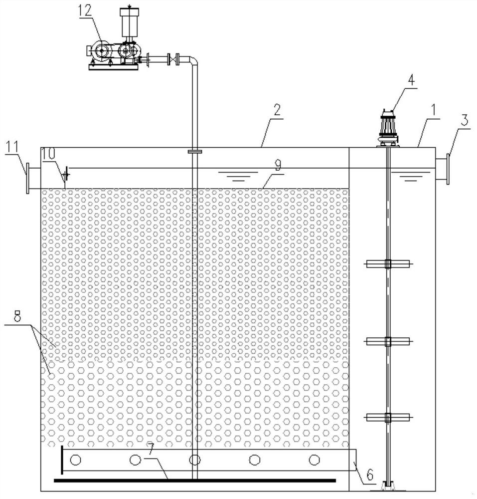
[0029] The post denitrification filter of the present invention is usually located at the rear end of the secondary sedimentation tank and the front end of the high-efficiency sedimentation tank, and the post denitrification filter includes a carbon source mixing reaction zone 1 and a nitrification reaction zone 2 . The effluent from the secondary sedimentation tank enters the carbon source mixing reaction zone 1 through the water inlet pipe 3, and the carbon source is added in this zone, and the sewage and the carbon source are fully mixed under the ag...


PUM

PropertyMeasurementUnit
pore sizeaaaaaaaaaa
particle diameteraaaaaaaaaa

Abstract

The invention discloses a rear denitrification filter tank. The rear denitrification filter tank comprises a carbon source mixing reaction zone and a denitrification reaction zone, the carbon source mixing reaction zone is provided with a mixing stirrer and a carbon source adding system, and the denitrification reaction zone is provided with a water distributor, an aeration system, a filter plateand a water outlet tank; the two zones are communicated through a water distributor at the bottom; a filter plate with a horizontal position lower than the orifice of a water inlet pipe is arranged atthe upper part of the denitrification reaction area, is of a planar structure with filter holes and completely covers the water outlet surface at the upper part of the denitrification reaction area;a water outlet groove is formed in the periphery of the upper water outlet surface of the denitrification reaction area and communicated with a water outlet pipe; and a filter material is put into thedenitrification reaction area below the filter plate. A light composite filter material is adopted, an upward flowing mode is adopted, the water inlet direction is consistent with the nitrogen release direction, nitrogen release is better facilitated, the nitrogen release process does not need to be independently set, rising of dissolved oxygen caused by downward flowing and water falling is avoided, and the carbon source adding amount is reduced; water head loss is small, and elevation arrangement is facilitated.

Description

technical field [0001] The patent of the invention belongs to the technical field of sewage treatment, in particular to the technical field of design and application of sewage treatment equipment, and specifically relates to a high-efficiency post-denitrification filter for deep denitrification treatment of sewage after secondary treatment. Background technique [0002] At present, the discharge standards of most sewage treatment plants in my country implement the first-level A standard of the "Pollutant Discharge Standards for Urban Sewage Treatment Plants" (GB18918-2002). With the higher requirements of human beings on the environment and the release of higher emission standards in various places, the new standards will have stricter requirements on total nitrogen emissions. Most of the existing sewage treatment plants use UCT (Univerdity of Cape Town), SBR (sequential activated sludge process), A 2 BOD 5 The removal rate ranges from 85% to 95%, the total nitrogen remova...

Claims


Application Information

Patent Timeline
Patent Type & Authority Applications(China)
IPC IPC(8): C02F3/28
CPCC02F3/2826C02F2305/06
Inventor 张进罗建辉
Owner 四川省科学城天人环保有限公司
Why Eureka
Try Eureka