An anti-jamming network and its application

A network and inductance technology, which is applied in the direction of amplifier input/output impedance improvement, amplifier improvement to reduce noise impact, amplifier, etc., can solve the problems of deteriorating amplifier noise figure, gain, lack of interference suppression technology, and increasing system complexity, etc., to achieve Achieve the effects of interference signal suppression, novelty, versatility, and compact structure

Active Publication Date: 2021-06-25
SOUTHEAST UNIV +2
View PDF0 Cites 0 Cited by
  • Summary
  • Abstract
  • Description
  • Claims
  • Application Information

AI Technical Summary

Problems solved by technology

[0008] The purpose of the present invention is to provide an anti-jamming network to solve the problem that the traditional radio frequency / millimeter wave frequency band interference suppression technology is not strong enough to suppress interference; and to provide the application of the high-order transformer coupling network with interference suppression in the amplifier circuit, to Solve the problem that the traditional circuit unit used to suppress interference signals in the RF / millimeter wave frequency band will deteriorate the noise figure and gain of the amplifier, increase the DC power consumption, and increase the complexity of the system, as well as the lack of adjacent channel interference suppression technology in the RF domain / millimeter wave domain question

Method used


Image

  • An anti-jamming network and its application
  • An anti-jamming network and its application
  • An anti-jamming network and its application

Examples


Embodiment 1

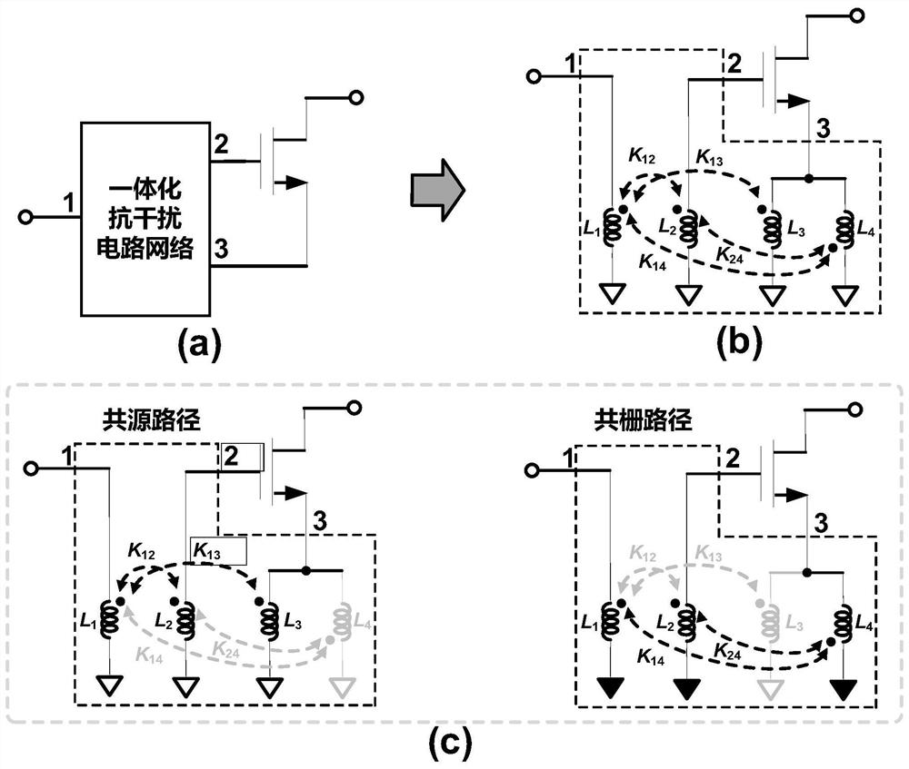
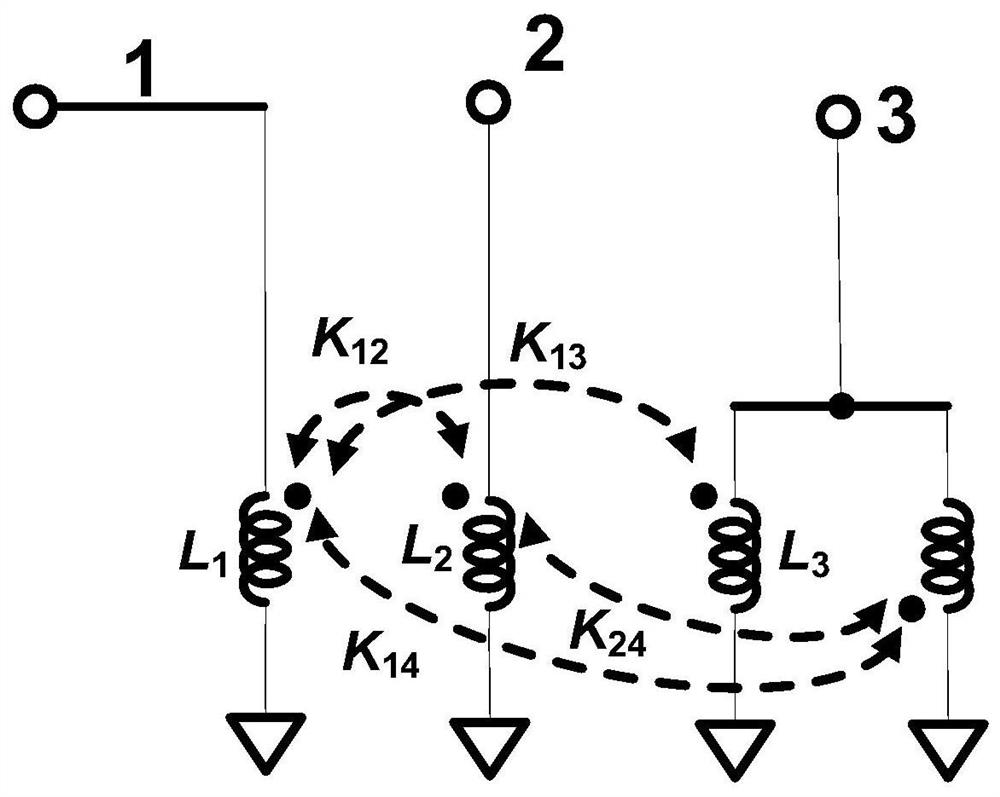
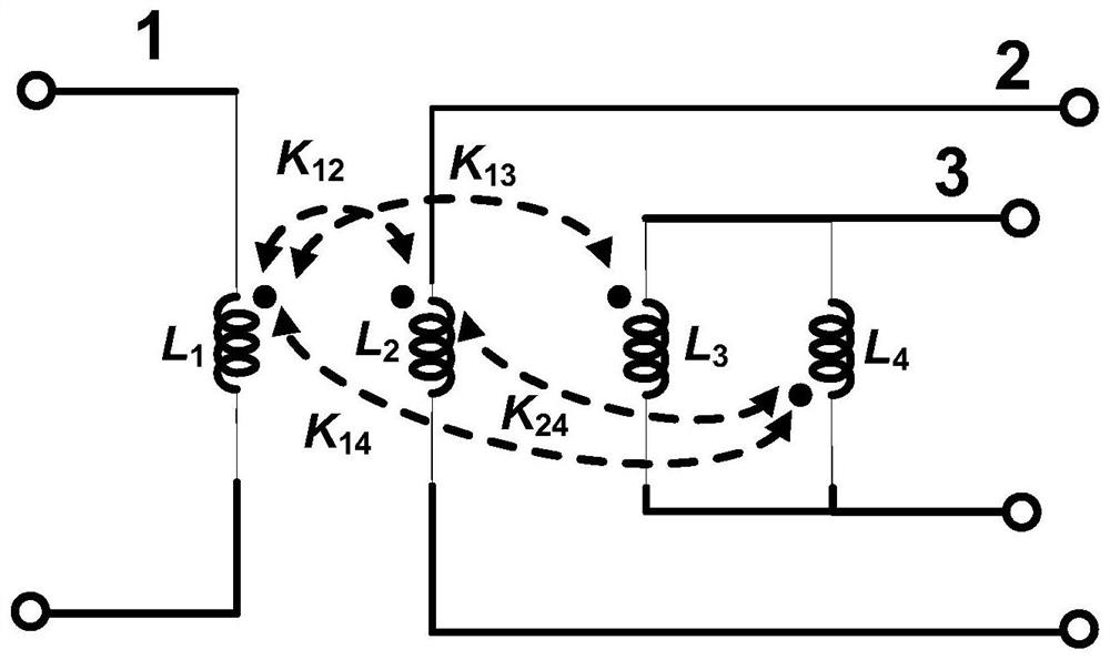
[0028] Embodiment 1: as figure 2 As shown, the anti-interference network described in the example of the present invention includes four inductance coils, two of which are connected in parallel, and these four inductance coils form a three-port high-order transformer coupling network. The negative terminals of the included first to fourth inductance coils are all connected to the ground terminal. The positive end of the first inductance L1 is connected to the input end, there is a coupling coefficient K12 between the first inductance L1 and the second inductance L2, there is a coupling coefficient K13 between the first inductance L1 and the third inductance L3, and there is a coupling coefficient K13 between the first inductance L1 and the fourth inductance L1. A coupling coefficient K14 exists between the inductors L4, a coupling coefficient K24 exists between the second inductor L2 and the fourth inductor L4, and the third inductor L3 and the fourth inductor L4 are connecte...

Embodiment 2

[0033] Embodiment 2: as Figure 6 As shown, the example of the present invention discloses a single-ended low noise amplifier with a transformer coupling network for interference suppression. Port 1 of the anti-interference network is connected to the input terminal, port 2 is connected to the gate of the first transistor M1, and port 3 is connected to the source of the first transistor M1. The gate of the first transistor M1 is connected to one end of the first resistor R1, and the other end of the first resistor R1 is connected to VB. The drain of the first transistor M1 is connected to one end of the fifth inductor L5, and the other end of the fifth inductor L5 is connected to VDD. One end of the sixth inductor L6 is connected to the gate of the second transistor M2, the other end of the sixth inductor L6 is connected to the ground, and there is a coupling coefficient K56 between the fifth inductor L5 and the sixth inductor L6. The gate of the second transistor M2 is conn...

Embodiment 3

[0034] Embodiment 3: as Figure 7As shown, a differential low noise amplifier with a transformer coupling network for interference suppression disclosed in the example of the present invention, the positive terminal of port 1 is connected to the positive input terminal, the negative terminal of port 1 is connected to the negative input terminal, and the positive terminal of port 2 It is connected with the gate of the first transistor M1, and the negative terminal of port 2 is connected with the gate of the first transistor M2. The positive end of port 3 is connected to the source of the first transistor M1, and the negative end of port 3 is connected to the source of the first transistor M2. The middle taps of the third inductance L3 and the fourth inductance L4 of the parallel inductance in the anti-interference network are grounded, or the middle taps of the third inductance L3 and the middle taps of the fourth inductance L4 are either grounded, and the first inductance of t...


PUM


Abstract

The invention discloses an anti-interference network and its application. The anti-interference network includes four inductance coils, that is, the first to fourth inductance coils. The anti-interference network is realized by the coupling effect between the inductance coils. There are two coils For parallel connection, these four inductance coils form a three-port high-order transformer coupling network. The input and output transfer functions have frequency selective characteristics. The low noise amplifier using this anti-interference network can effectively suppress out-of-band interference signals. And the anti-interference high-order transformer coupling network adopted will not deteriorate the noise figure, gain and other indicators of the amplifier, and will not increase the DC power consumption at the same time.

Description

technical field [0001] The invention relates to an anti-jamming network and its application, belonging to the field of circuits and systems, in particular to the technical fields of radio frequency and analog integrated circuits of microelectronics and solid electronics. Background technique [0002] With the rapid development of wireless communication technology in recent years, portable terminals such as smart phones and tablet computers have gradually become indispensable tools in people's daily life. It is very important to design large wireless transceivers with low power consumption and high integration. Due to the coexistence of multiple wireless systems and complex application scenarios, each transceiver faces serious interference from other transceivers and also needs to withstand its own self-interference. Therefore, interference suppression technology is the core and key technology in broadband wireless transceivers. [0003] In wireless transceivers, the design o...

Claims


Application Information

Patent Timeline
Patent Type & Authority Patents(China)
IPC IPC(8): H03F1/02H03F1/26H03F1/56
CPCH03F1/0205H03F1/26H03F1/565
Inventor 张有明唐旭升黄风义孙一龙余正义李俊杰姜楠
Owner SOUTHEAST UNIV
Why Eureka
Try Eureka